Resources
Requirements
- info 3DS Max 2011 Design, RailClone Pro 2.x, Forest Pack Pro 4.2
Introduction
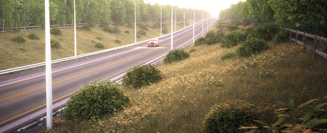
In this Tips and Trick Tutorial we look at how RailClone and Forest Pack can be used with Civil View in 3DS Max Design. Civil View streamlines the process of sending data from Autodesk Civil 3D to 3DS Max Design to help Civil Engineers easily create compelling visualisations of their projects. Importing a Civil 3D project into 3DS Max via Civil View automatically generates surfaces and textured roads from corridor, roundabout and intersection tools used in Civil 3D. In addition Civil View will generate paths and feature lines that can be used to add further 3D content in 3DS Max.
It's therefore simple to replace Civil View's modelling tools with RailClone. Like Civil View, RailClone is a style driven plugin allowing for the quick and easy addition of common 3D assets to a visualisation. However, RailClone's modelling tools and ability to use native render shaders to render huge polycounts is considerably more flexible than Civil View's, making RailClone a logical choice for use in high end civil visualisations. In addition we will look at how Forest Pack can be used to easily add foliage and trees to Civil View surfaces, using corridor splines to help further refine scatter areas.
In this tutorial we'll look at how to get started with RailClone and Forest Pack by adding common 3D elements to a scene imported from Civil 3D. By the end of this tutorial you will be able to:
- import Civil 3D data using Civil View
- add street lighting an road markings with RailClone to paths and feature lines generated by Civil View
- create a RailClone bridge driven by corridor paths
- add foliage using Civil View surfaces
- add foliage using Civil View corridor paths
Download Contents
The scene files that accompany this tutorial contain the following files:
- intro_civil_view_start.max. The starting scene file for this tutorial.
- bridges.max. A replacement bridges file for the RailClone library optimised for use with Civil View.
This tutorial uses the Civil 3D New Road Design.vsp3d dataset from the Civil View for All, Autodesk university session. The file can be found in the additional class materials download. (Unfortunately, these files are no longer available, you can still follow the majority of this tutorial using Max's native splines)
Part 1 - Importing the Dataset
There is no difference when importing Civil 3D data whether you are using Civil View objects or RailClone. Both Civil View and RailClone can use exactly the same splines as paths to generate parametric geometry.
- Open intro_civil_view_start.max
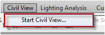
- Go to the Civil View drop down menu at the top of the 3DS Max interface and select Start Civil View...
![Civil View Interop.-startCivil.png]()
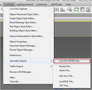
- Now go to Civil View>Geometry Import>Civil View (VSP3D file) ...
![Civil View Interop.-startCivil2.png]()
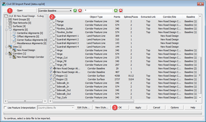
- From the Civil 3D import panel click Open and load the file named Civil 3D New Road Design.vsp3d. This can be found in the course files from this Autodesk University course.
![Civil View Interop.-civilImport.png]()
- From the Item List select the elements listed in the first column from the table below and press OK. The right column describes the objects that are generated by Civil view that can be found in the scene after import. We can now use these objects to add lights, road markings, crash barriers, a bridge and foliage to the scene.
Existing Creek
C3Dsurface-C-TOPO-Existing Creek
Existing Ground - Civil View
C3Dsurface-C-TOPO-Existing Ground - Civil View
New Road Design Alignment
C3Dbaseline-New Road Design Corridor-New Road Design Alignment
New Road Design Alignment
C3Dbaseline-New Road Design Corridor-New Road Design Alignment
Region (1)
C3Dsurface-New Road Design Corridor-Region (3)
Region (3)
C3Dsurface-New Road Design Corridor-Region (1)
Bridge Endcap North
C3Dsurface-C-TOPO-Endcap North
Bridge Endcap South
C3Dsurface-C-TOPO-Endcap South
As you will see there are many other potential paths available but for this example we can drive all the RailClone and Forest pack objects from these few splines generated by the corridor alignments.
Part 2 - Using RailClone with Civil View
Because Civil View automatically generates splines from road alignments and feature lines, it's easy to add RailClone objects to imported Civil 3D scenes. In the first part of the tutorial we will quickly populate a road using items from the RailClone library.
Adding the road markings
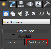
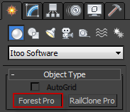
- Create a new RailClone object by going to the Command Panel>Create>Geometry>iToo Software. Select RailClone and drag out a new object anywhere in the scene.
![Civil View Interop.-railclone1.png]()
- RailClone comes with a large library of ready-to-use styles. To open the library, go the the ModifyPanel, Style rollout and press the large button that currently says none
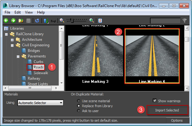
- The library browser will open. From the library navigator on the left, find Civil Engineering>Pavements>Roads and select a line marking style for the centre of the road. In this example we'll use Line Marking 4.
![Civil View Interop.-library lines.png]()
- Press the Import button
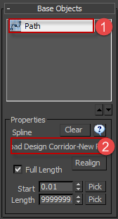
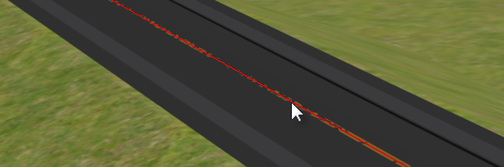
- We need to tell RailClone which spline to use as a path. Go to the Base Objects rollout and select Path from the list. From the spline properties section, press the spline name button currently marked None and select C3Dbaseline-New Road Design Corridor-New Road Design Alignment from the scene.
When Civil View created the splines it automatically names them based on their Civil 3D properties. In this case there are two alignments with identical names. You need to select the spline that runs the full length of the road, the other defines just the bridge section.
![Civil View Interop.-pick path.png]()
![Civil View Interop.-pickspline.png]()
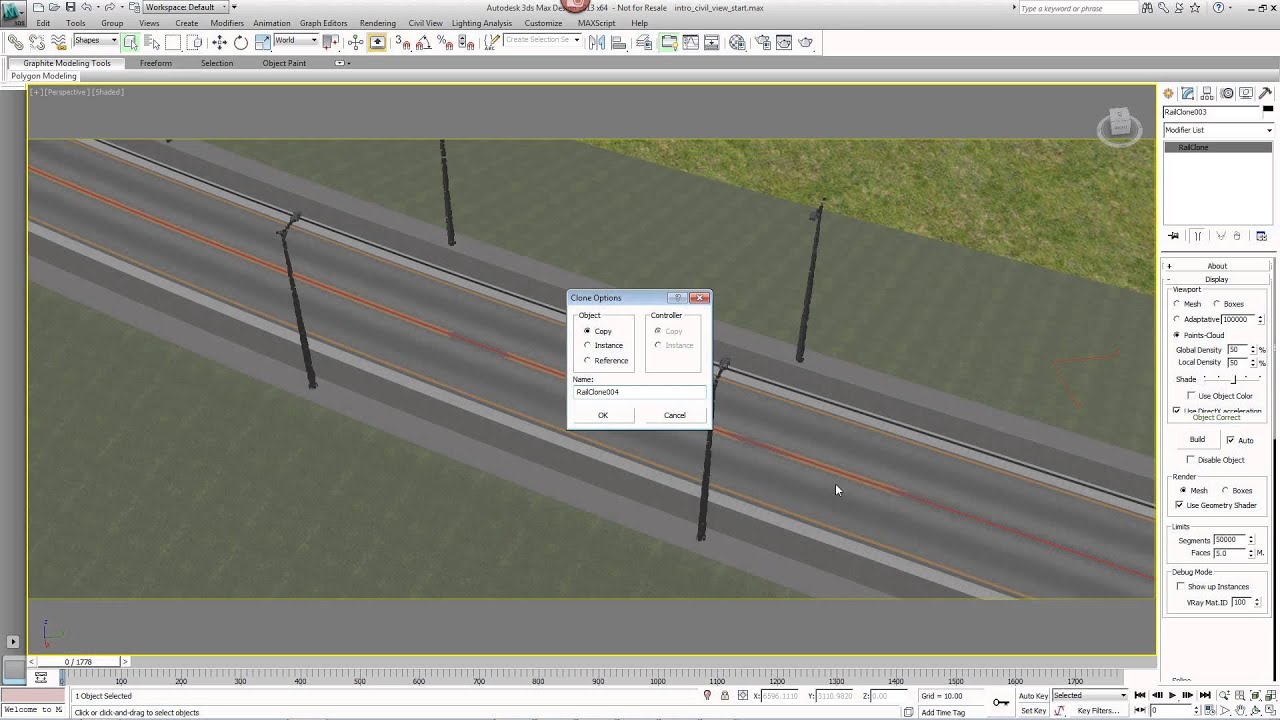
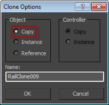
- You will now have road marking running down the centre of the road. To create marking either side of the road duplicate this RailClone object by pressing CTRL+V. Make sure that copy is selecting from the subsequent Clone Options dialog box.
![Civil View Interop.-cloning.png]()
- We can now retain the spline allocation but switch the geometry by accessing the library and selecting a new style. Reopen the library using the same process as described in step 2.
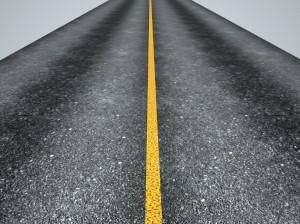
- Select Civil Engineering>Pavements>Roads>Line Marking 1 and press Import. The single line style is in the centre of the road but we need it on either side. To do this we need to make a couple of simple edits to the ruleset that drives the style.
![Civil View Interop.-_rc_marking_1.jpg]()
- To edit a style use the style editor, this can be opened by pressing the Style Editor button from the Style Rollout
![Civil View Interop.-rc_button_editstyle.png]() .
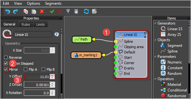
. - You will see RailClone node based editor. Blue nodes are generators, these define a set of construction rules used to create one and two dimensional arrays driven by splines. To adjust these rules, simply select the generator and its properties will be visible in the tabbed panel on the left of the style editor.
- We want to create two lines from a single spline to do this turn On the Mirror option from Properties>General>Geometry.
- To offset the lines on either side of the road alignment spline, enter a value of 11 in the Y Offset property. You will now have road markings that run the full length of the road.
![Civil View Interop.-changingLines.png]()
 .
.
Adding the lights
- Now create a copy of the second line style to create the crash barriers. With the line RailClone object selected press Ctrl+V to duplicate.
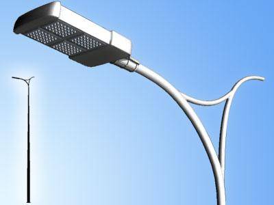
- Open the library browser and change the style to Civil Engineering>Street Lights>Street Light 2.
![Civil View Interop.-streetlight_2.jpg]()
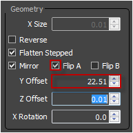
- Open the style editor and change the Y Offset value to 22.5. To flip the lights so that they both point toward the centre of the road turn on Flip A.
![Civil View Interop.-streetLightOffset.png]()
Adding the Crash Barriers
- Duplicate the Lights RailClone Object by pressing CTRL+V.
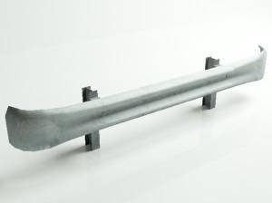
- Open the Library and change the style to Civil Engineering>Traffic>GuardRail Steel 2.
![Civil View Interop.-_rc_guardrail_3.jpg]()
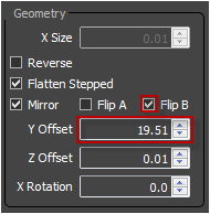
- Open the style editor and turn change the Y Offset value to 19.5. Turn on Flip B
![Civil View Interop.-guardRailSettings.png]()
- Crash barriers will now run the length of the road.
Adding the Bridge
- Finally we can use RailClone to easily add a bridge. To do this create a new RailClone object anywhere in the scene.
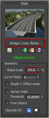
- Open the library and select Civil Engineering>Bridges>Bridge 1 Way 3 Lanes (NB this tutorial is using a modified version of the bridge library files. These new versions use the spline to define the top of the bridge, not the bottom and are included in the download files for this tutorial. To replace them in your library simply copy and replace the existing file found by default in c:\Program Files (x86)\Itoo Software\RailClone Pro\lib\default1\Civil Engineering\Bridges\.
- From the Base Objects rollout assign the spline called C3Dbaseline-New Road Design Corridor-New Road Design Alignment. The bridge will be in place but too small.
- Go to the Style rollout and increase the Global Scale until he bridge width matches the road.
![Civil View Interop.-bridge.png]()
Part 3 - Using Forest Pack with Civil View
Like RailClone, we can use the splines and surfaces created by Civil View to carefully place foliage without any need to add additional base objects in Max.
Adding Trees
Click to enlarge
- Go to Create Panel>Geometry>iToo Software and select Forest Pack. Create a new Forest Pack Object by picking C3Dsurface-C-TOPO-Existing Ground - Civil View from the scene.
![Civil View Interop.-forest1.png]()
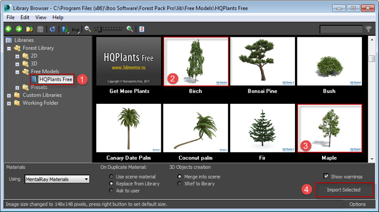
- To select some 3D trees for the scene go to the Geometry rollout and press the Library button to open the Library Browser.
- In the library browser go to HQ Plants Free and select Birch, hold down Ctrl to select multiple items and click Maple. Press Import Selected then delete the default item from the geometry list.
![Civil View Interop.-forestlib.png]()
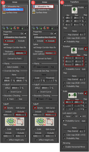
- At present the trees are covering the whole even area though the majority of the area will not be visible in the renders. To limit the trees to a set distance either side of the road corridor it's possible to use the same spline we used to drive all the RailClone objects. To do this open the Areas rollout, select Surface areas from the list and turn it off. Press the Add New Spline area button and pick C3Dbaseline-New Road Design Corridor-New Road Design Alignment from the scene. Change the Thickness value to 1500.
- To remove the trees from under the bridge and on the surface of the road, add another new Spline area and pick the same spline. Set the new spline area's mode to Exclude and change the thickness to 32. Turn on Falloff>Density and set the exclude value to 40.
- Add some variation by going to the Transform rollout and turn on Rotation. Turn on Scale and set the Min value to 80% and the Max value to 250%.
Adding Bushes
- To add bushes to the verge we will clone the forest object we just created by Pressing CTRL+V.
- From the Geometry rollout, delete one of the items and then with the remaining selected, open the Library and pick Bush from the HQ Plants Free category.
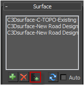
- To plant bushes on the verge we need to add the road geometry objects to the scatter. Go to the Surface rollout, click on Add Multiple Surfaces (
![Civil View Interop.-button_addmultiple.gif]() ) and select C3Dsurface-New Road Design Corridor-Region (1)and C3Dsurface-New Road Design Corridor-Region (3) from the scene.
) and select C3Dsurface-New Road Design Corridor-Region (1)and C3Dsurface-New Road Design Corridor-Region (3) from the scene. - Go the the Distribution rollout and decrease the Density to 700.
![Civil View Interop.-density.png]()
- Finally to bring the bushes closer to the road, from the Areas rollout decrease the Exclude spline's Thickness to 27 and turn Off Falloff>Density.
 ) and select C3Dsurface-New Road Design Corridor-Region (1)and C3Dsurface-New Road Design Corridor-Region (3) from the scene.
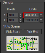
Adding Grass
- To add grass we'll use a preset. This is a library object that includes all the information necessary to create a scatter. All that remains is to identify the planting areas. To get started create a new forest object and select C3Dsurface-C-TOPO-Existing Ground - Civil View from the scene.
- From the Surfaces rollout, add C3Dsurface-New Road Design Corridor-Region (1)and C3Dsurface-New Road Design Corridor-Region (3).
![Civil View Interop.-surface rollout.png]()
- Open the library browser and go to Presets>Grass. Pick any grass style but ensure it has the suffix [large]. These presets are optimised to fill large areas.
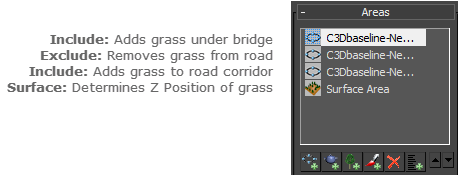
- From the Areas rollout, add the full road path as an include Spline area. Increase the Width so that the grass just crosses into the tree line.
- Add a second Spline area using the same path, this time set the mode to Exclude and increase the Width value until the grass disappears from the road surface.
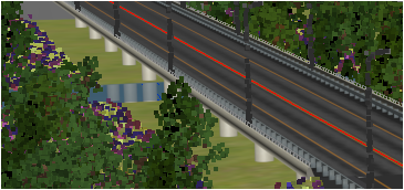
- You'll notice that the grass has disappeared from below the bridge.
To fix this add a third spline area, this time set to Include, and pick the bridge spline from the scene. Adjust the Width so that the grass fills in the void.
![Civil View Interop.-grass_disappear.png]()
![Civil View Interop.-preset_areas.png]()
Conclusion
In this tutorial we looked at how RailClone and Forest pack can be used with Civil View to quickly populate a scene with parametric 3D objects and foliage. In this example we used objects from the built in libraries but by using RailClone's node based approach to modelling, it's easy to create powerful custom styles for civil applications. Stay tuned for future tutorial on bridge modelling and much more or for more tutorials on RailClone 2 please visit our tutorials page and YouTube channels or follow us on Facebook and Twitter.
Or if you're a Civil 3D user who would like to find out more about how Civil View and 3DS Max Design can be used to create visualisations, these sessions from Autodesk University are a good place to start.
- Producing Compelling Visualizations for Civil Engineering Project Proposals
- Delving Deeper: Mastering the Autodesk Civil Visualization Extension
- Feeling the Lay of the Land: AutoCAD Civil 3D and Autodesk Civil View for Landscape Architects
- Add Life to Your Visualization Using Traffic Simulations with Civil View Tools in 3ds Max Design