Resources
Requirements
- info RalClone Pro
Introduction
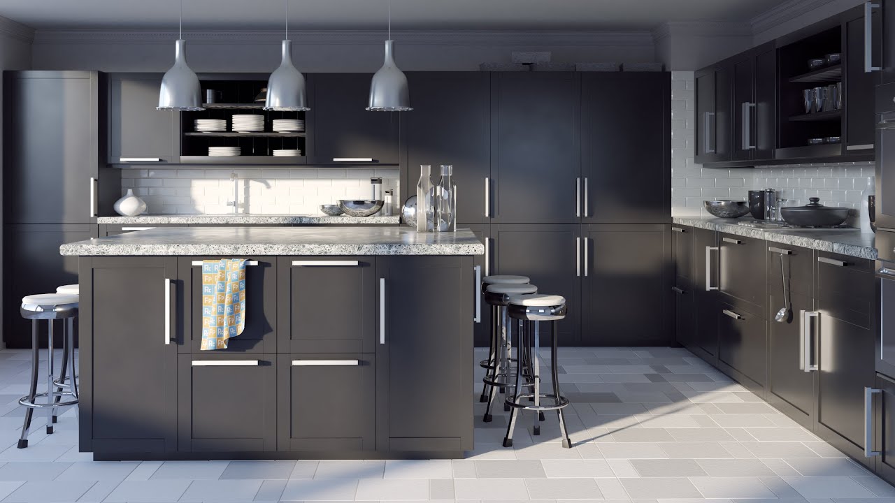
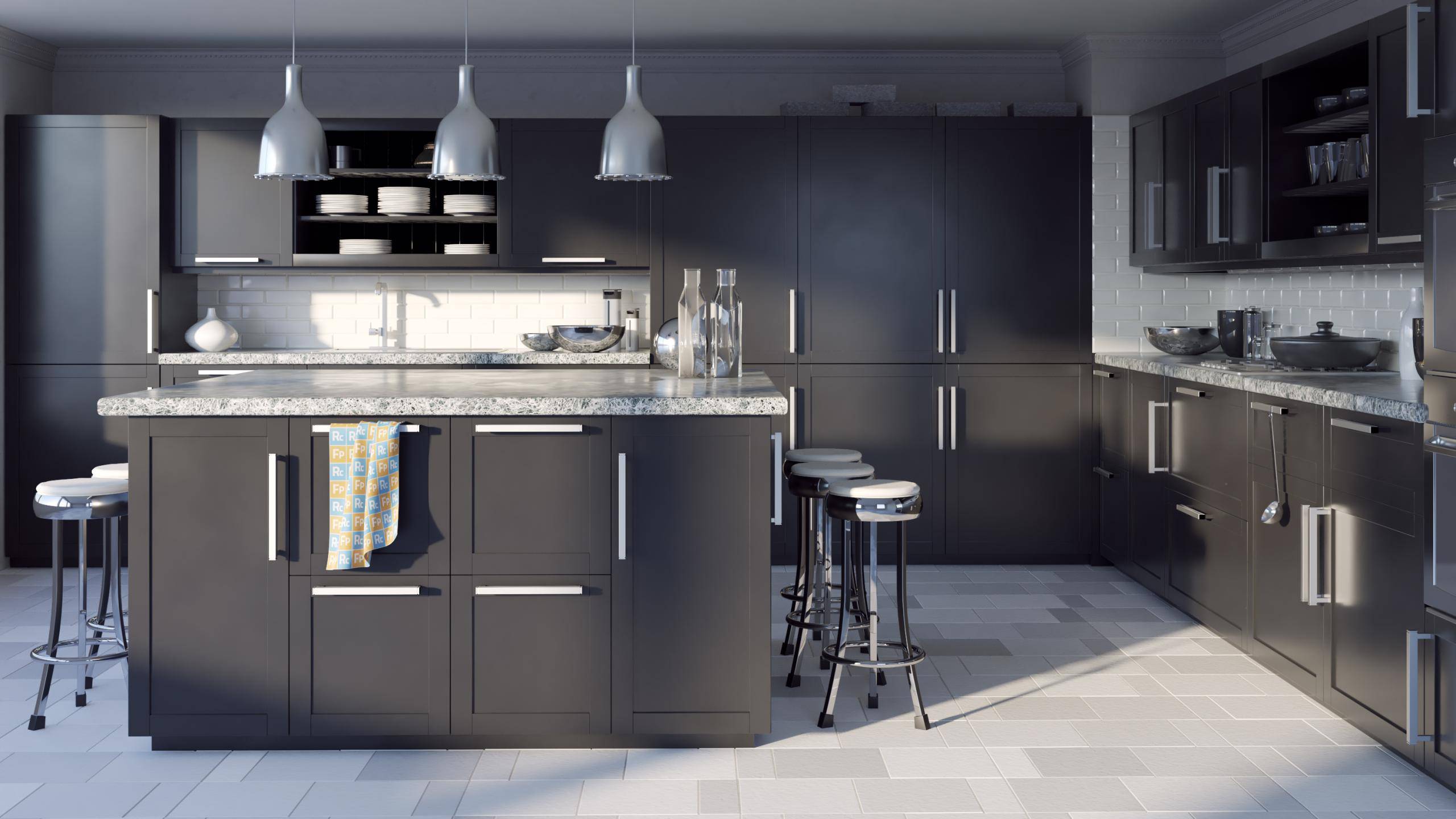
In this tutorial we share a style for RailClone to help create cupboards and kitchen units. In the first half we'll take a detailed look at the style supplied in the downloads for this tutorial, showing how you can change door types and their hanging direction just by making simple changes to the base spline. This is ideal for quickly creating kitchen layouts and best of all this style is easy to reuse, so once you've understood it ,you should only have to swap the geometry for any new kitchen of other types of cupboards that you want to create.
In the second half, aimed at advanced users, we'll take a closer look at how to create a style like this from scratch including the strategy of breaking down a style into several interdependent generators - a common approach for more complex styles.
By completing this tutorial you will be able to:
- Use the supplied style to create kitchen cabinets.
- Adapt the supplied style to use your own geometry.
- Create styles with multiple generators.
- Use Material IDs to select segments.
- Use Vertex Types to select Segments.
- Use the conditional operator
- User Exported parameters and attributes to create numerical relationships between nodes.
Part 1 - Using the pre-built Style
You may never need to actually create this style from scratch. Instead we'll demonstrate how it works and illustrate how you can adapt it for your own needs by preparing and swapping geometry as required. Let's start by looking at the basics of how you would use the style to create a simple kitchen layout.
Spline controls and parameters
- The entire object is driven by a single spline. By editing the spline's material IDs, line and vertex types you can control many aspects of the design. There are also additional settings found in the Parameters rollout of the Modify Panel.
![Kitchen Cabinets with RailClone-image2016-6-23 17:2:12.png]()
- The height of the worktop and cabinets it derived automatically from the doors so if you change the door geometry and the rest of the style updates automatically.
- Doors are created by adding vertices. One single door is scaled automatically between two vertices. Doors are prepared so that only the mid-sections scales, minimising the chance of incorrect deformation on the sides.
- Different types of door are selected by changing the Material ID on the spline segment, as you change the ID you'll see the type of door updates in real-time so you can quickly lay out a kitchen.
- To change the hanging direction of a door you change the type of the vertex preceding the section. A corner vertex causes the door to hang from the left and a corner-bezier vertex hangs the door from the right.
- If there's a change in cupboard height, for example you want worktop height and larder height cupboards on the same spline, you'll need to break the vertex at the point where this changes. This is so that the height of the cabinet's sides can be recalculated for the larger door and continue past the height of the worktop.
- You may not always want a worktop on top of the cupboards, especially for larders or you're using the style for wall cupboards. In this case you can turn off the worktop by selecting spline segments, then right-click and and change the type to Curve.
![Kitchen Cabinets with RailClone-image2016-6-23 16:53:51.png]()
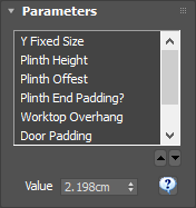
- That covers the parts of the style that can be modified using the spline. There are also a number of useful parameters found in the modify panel. The first of these is the Y Size parameter that is used the adjust the depth of the cupboards. Everything is linked to this so when it's changed it affects the cupboards, door position, plinth and cabinets.
- The height of the plinth can also be adjusted using the Plinth Height parameter. As you can see when this is adjusted everything above is also moved.
- Plinth Offset is used to push the plinth back underneath the cabinet and Plinth End Padding lets you choose if this effect should also be applied to the ends.
![Kitchen Cabinets with RailClone-image2016-6-23 17:50:25.png]()
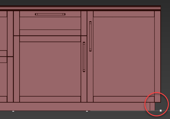
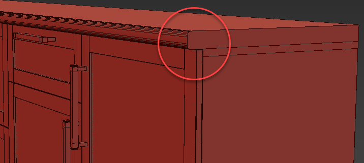
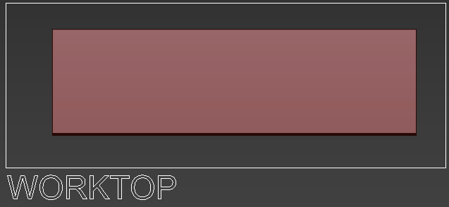
- Worktop Overhang is used to extend the worktop over the cabinets. You can also use a negative value to reverse the effect if necessary.
![Kitchen Cabinets with RailClone-image2016-6-23 17:51:23.png]()
- Finally Door Padding can be used to adjust the gap surrounding the doors. When combined with Door Offset you canalso use this parameter to decide if the door is housed inside the frame, or mounted on the face of the cabinet.
Changing the geometry
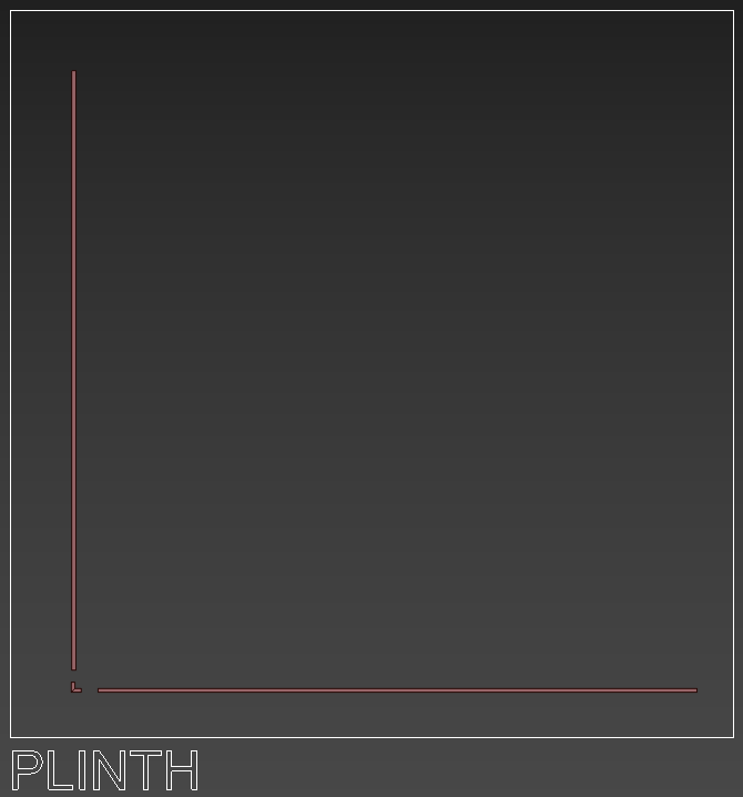
Now we know how to use the style, let's take a look at how you can use your own geometry. The various elements have to be prepared in a particular way, but it's no more complicated that slicing your pre-modelled doors and other parts into sections so they can be easily scaled to different sizes. Normally you'd need a number of different doors and carcasses in different widths, but with this style you just need one for each type of door or draw combination. Starting at the bottom of the kitchen we find a plinth which is divided into 3 parts, a corner and two sides.
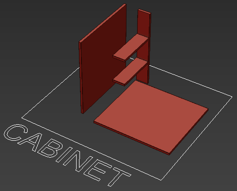
Above this, the cabinet is divided into the 3 parts: The bottom, the sides and the back. If necessary you could also add the top of the cabinet as an extra segment, but in my example I'm just reusing the bottom.
On top of the cabinet we have the worktop which is a single object. Nothing special here.
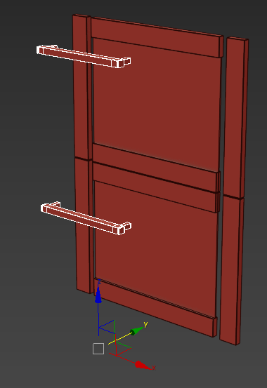
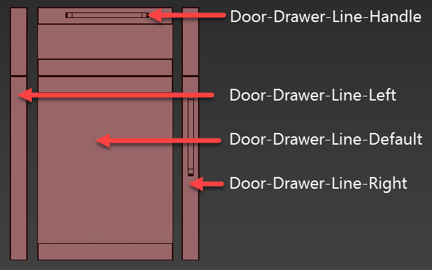
Finally we have the doors, these involve the most work because we need to separate them into those parts that can be stretched on the X axis and those that must remain the same size to avoid distortion. This usually involves splitting them into 3 parts, with two fixed size sides and a third section in between that scales to fill the available space. Any handles on the doors should be placed on the right hand segment as show below.
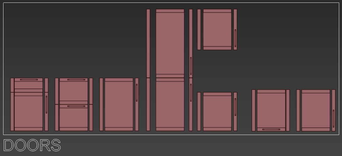
Handles in the centre of the width of the unit will need to be separate objects with the pivot aligned to the bottom of the door.
This is all you need to create a flexible kitchen style using this RC object. To add these pieces to the RailClone Style you would use the existing style and following these steps:
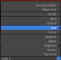
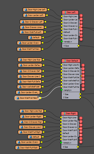
- Open the Style Editor. If you're not experienced with RailClone the graph can look a bit daunting but don't worry you only need to locate and change the Orange Segment nodes, they look like this and normally display the name of the geometry selected from the scene.
![Kitchen Cabinets with RailClone-image2016-6-24 11:48:12.png]()
- It's most likely the doors you will want to change. To do this locate the clusters of segment nodes attached to 3 Selector nodes called Door Left, Door Default, and Door Right. These segments relate to the door pieces we saw earlier, the order that they are connected to the Selector operators determines the material ID number used to assign them to a spline section. Starting from the top the material IDs increase for each additional connection, so in this graph at the moment there are 8 different door type that can be selected. To add more just connect additional segments.
![Kitchen Cabinets with RailClone-image2016-6-24 11:54:43.png]()
- Let's add a door so that it is selected using Material ID 1. Remember it is made of 3 parts (4 if you include the centred handle)
![Kitchen Cabinets with RailClone-image2016-6-24 11:59:13.png]()
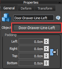
- Select the first Segment node connected to the Selector operator called Door Left.
- Go to the Properties Panel, Click the Object Picker button and Door-Drawer-Line-Left from the scene.
![Kitchen Cabinets with RailClone-image2016-6-24 12:8:26.png]()
- Now do the same for the other two selectors, making sure that the same input is used in each so that the IDs will match. Select the first Segment node connected to the Selector operator called Door Default.
- Go to the Properties Panel, Click the Object Picker button and Door-Drawer-Line-default from the scene.
- Finally select the first Segment node connected to the Selector operator called Door Right.
- Go to the Properties Panel, Click the Object Picker button and Door-Drawer-Line-right from the scene.
- Keep following this procedure to add any additional doors. Once you've done this you can check the style by applying it to a spline and changing the material ID. Each ID change should give you a different door.
- Where a door needs centred handles these are added separately using the Selector operator called Centred Handles. There should be the same number of inputs as we saw with the door selectors, this is because each one of these inputs corresponds to the same material IDs as the door secgments. Even if no handle is needed, it's important to add a null segment so that the number of inputs remains the same and in sync.
- It's also possible to change all the other geometry elements, for example to change the Worktop, find the segment with the same name and pick your geometry from the scene.
- To change the cabinet, use Frame-Back, Frame-Side and Frame-Bottom.
- To change the plinth, use Plinth-Side, Plinth-Top and Plinth-Corner.
By adding or changing these segments you should be able to create a wide range of cabinet and door types. But in the next section we'll learn how to create this style yourself from scratch for a deeper understanding of RailClone.
Part 2 - Creating the Style from Scratch
For advanced users who'd like to build a style like this from scratch I'll demonstrate how this is done, The focus here is on the creation of several different but interconnected generators to create a style that adapts to the segments and base objects added to it. Also almost all of the dimension values are extracted automatically from the segments so that the style can be really easily update either using parameters or by adding new geometry.
Creating the plinth
We'll start at the bottom with the plinth. There's already a RailClone object in the scene we can use for this exercise. It's largely empty with the exception of the segments that have been added to save a little time later. These are at their default settings except the Alignment > Y setting which is changed to top to align with the base spline correctly, as we'll see.
- Create a new A2S generator.
- Create a new Spline node, pick a spline from the scene and wire it to the Generator's X Spline Input
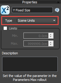
- We'll set the depth of the cabinets using a parameter. To do this right-click on the Generator and export the Y Size property.
- Create a new Numeric node and wire it to the exported Y Size property. Change the Numeric node's mode to Scene Units.
![Kitchen Cabinets with RailClone-image2016-6-28 15:46:4.png]()
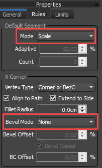
- Set the Generator's Default > Mode to Scale. This is so that the plinth segment will scale along the length of the spline without getting sliced. You should also change Bevel Mode to None to prevent the spline being sliced at each vertex change. This will maximise the amount of instancing that takes place as sliced segments render as static geometry.
![Kitchen Cabinets with RailClone-image2016-6-28 15:46:55.png]()
- Now we'll add the geometry. Wire Plinth-Side to the Generator's Left input. Also wire it to the Right input via a new Mirror operator.
- Wire Plinth-Top to the Generator's Bottom input.
- Wire Plinth-Corner to the Generator's Left Bottom Corner input. Wire it to the Right Bottom Corner input via a new Mirror operator.
- We'd also like a parameter to control the height of the plinth. To do this click on each of the plinth segments and export Z Fixed Size. Wire these to a new Numeric node and call it Plinth Height. Change the type to Scene Units.
- We'd like the spline for this style to be at the back of the cabinet, near the wall. At the moment the spline is at the front. To fix this we need to negatively offset the geometry on the Y axis the same distance as the Y Size. To do this, Export the Generator's Y Offset
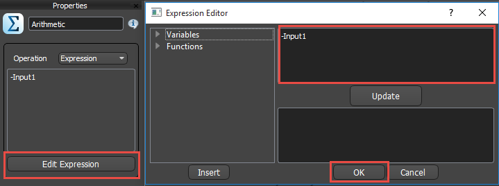
- Now we need to return the negative of the output from the Y Size node. The way to do this with the fewest nodes is to add an Arithmetic operator, change the mode to Expression and enter -Input1 into the expressions editor. Wire the Y Size node to the arithmetic node and then wire the arithmetic node to the generator's exported Y Offset input. If you get an error message, in this case it can be ignored because you're not using any incompatible features and it'll work fine. You can now adjust the depth of this from the Modify Panel and the plinths's back is aligned with the spline!
![Kitchen Cabinets with RailClone-image2016-6-28 15:49:20.png]()
- To make this style a little more flexible we also want the ability to offset the plinth so that it's stepped in from the cupboard fronts. In this setup the Y Size will set the cabinet depth and then we'll deduct from this a Plinth offset. To this, create another Numeric node and set the type to Scene Units. Name this node Plinth Offset.
- Create a new Arithmetic node and set the mode to Subtract. Wire Y Size to the first input and Plinth Offset to the second input. Wire the arithmetic node to the Generator's Y Size input, and the Y Offset via the existing arithmetic node.
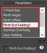
- Nearly there! Now we have the padding we want to provide an option to add it to the ends of the generator too. To do this we need another numeric node to act as a toggle to turn this feature off and on. So create a new Numeric operator and set the mode to Boolean. Call this node Plinth End Padding?
![Kitchen Cabinets with RailClone-image2016-6-28 15:50:43.png]()
- Wire Plinth End Padding? to a new Arithmetic node and change the mode to Expression. Open the expressions editor and enter if(Input1=1,Input2,0). Wire the Plinth Offset node to Input 2. This expression is now saying ... "If plinth end padding is turned on, return the value in input 2 (the plinth offset), otherwise just output 0".
- Select the generator and export Limits > Padding Start and Padding End andwire them to the arithmetic node created in previous step. Now you can toggle on and off the end padding, adjust the width, adjust the plinth offset, and change the height. In the next steps we'll start building the cabinet carcass.
Creating the cabinet bottom
To start the cabinet we begin with the base which should sit on top of the plinth we just created. To do this we'll start with a new separate L1S Generator, as I mentioned breaking things down is the easiest approach with this kind of object.
- First of all, Create a new L1S generator and wire the existing Spline node to the generator's Spline input. Change the Default > Mode to Scale and Bevel Mode to None.
- Wire the Frame-Bottom segment to the Default input.
- To adjust the depth of the cabinet, export the Y Fixed Size property of the segment and connect the Y Fixed Size numeric node.
- Lastly, the cabinet bottom is currently on the floor and we want it sat on top of the plinth. So to do this we need to add some Z Offset to the generator. Right-click on the generator and export Z Offset.
- Wire the Plinth Height numeric node to the Z Offset input. Now as you adjust the height on the plinth, the cabinet bottom moves up accordingly.
Creating the cabinet sides and back
With the bottom done we can add the back and back of the cabinets.To to do this:
- Duplicate the L1S Generator created in the previous step and remove the existing segments from the inputs.
- Wire a Transform operator to the Start, Corner and End inputs. This is so that we can control the height based on the size of other segments in the style. Right-click on the Transform operator and export the Z Fixed Size and Y Fixed Size parameters. Also export the X Size attribute because we'll use it later to create padding for the doors.
- Connect the Frame-Side segment to the Transform operator.
- To adjust the depth of the cabinet connect the Y Fixed Size numeric node to the Y Fixed Size input.
- In this style the cabinet height it automatically calculated based on the size of the door segments. To do this, find the existing Door Default selector operator, Right click on it and export the Z Size attribute. This will allow the height of the currently selected door to be piped to drive the height of the cabinet.
- Create a new Arithmetic operator and wire this attribute to the first input. Wire the Arithmetic operator to the Z Fixed Size input of the Transform operator created in step 2. This Arithmetic operator allows us to adjust the padding of the door, to do this add a new Numeric node, set the mode to scene units, and wire it to the arithmetic operator twice. You may wonder why twice? This is because you will be adding padding to the top and bottom of the door so we need double the value.
- That takes care of the sides. Now lets add the back. Wire a new Transform operator to the Default input. Right-click on the Transform operator and export the Z Fixed Size parameter.
- Wire the same arithmetic operator being used to control the height of the side to the Z Fixed size parameter of this node. Now both segments are deriving their height from the doors.
- Finally, we need the sides to start on top of the cabinet base so again we'll offset on the Z Axis. The correct offset value is the sum of the height of the plinth, plus the thickness of the base. To calculate this, create another Arithmetic node and wire the Frame-Bottom'sZ Size attribute and the Plinth Height numeric node to its inputs. Wire the Arithmetic node to the generator's Z Offset input. Now lets add the top to this cabinet.
Creating the cabinet Top
- Duplicate the L1S Generator created in the previous step and remove the existing segments from the inputs.
- Wire a new Transform operator to the Default input. Right-click on the Transform operator and export the Z Fixed Translation parameter. We're going to use this instead of the generator's Z Offset parameter to position the worktop. There's a good reason. The Generator's property offsets all segments in the style and the results are the same for all the spline sections, whereas the Translation value of individual segments allow you to adjust the height at any point. This means you can have cabinets of different heights on the same spline.
- Wire the Frame Bottom Segment to the Default input.
- To find the height we need to add together the height of the plinth, the height of the cabinet base, and the height of the sides. To do this we'll create another Arithmetic operator and connect the node driving the height of the previous generator, and the arithmetic node used to drive the height of the doors. That's the cabinets done, now let's add the worktop to the top of this.
Creating the worktop
The worktop is pretty straightforward but has one unique feature: It is only meant to appear when the segment type is a line, not a curve. To achieve this:
- Duplicate the L1S Generator created in the previous step once again and remove the existing segments from the inputs.
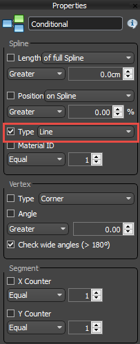
- Wire a Conditional operator to the Default input. we'll use this to detect the type of spline. Open the node's parameters and turn on Type, change the drop-down menu to Line.
![Kitchen Cabinets with RailClone-image2016-6-28 16:0:32.png]()
- Now wire a new Transform segment to the True input. Just like the we saw with the cabinet top, we'll use this instead of the generator's Z Offset parameter to position the worktop. Right click on it and export the Z Fixed Translation parameter.
- Let's create the sum for the Z offset. Create a new Arithmetic node and wire the Frame-Bottom'sZ Size output, and the arithmetic node driving the height of the cabinet top segments to the inputs.The order isn't important.
- Wire the new Arithmetic node to the Z Fixed Translation input of the Transform operator. The height it now set correctly
- Wire the Worktop segment to the Transform operator. Right-click on it and export Y Fixed size. We want the worktop to scale on the Y Axis to match the cabinets, though typically it would also overhang slightly. So we need to adjust the global Y Size numeric node with an offset parameter.
- To do this, wire a new Arithmetic node to the Y Fixed Size input of the Transform node.
- Wire the Y Fixed Size numeric node to the first input of the Arithmetic operator
- Create a new Numeric Node, change the type to Scene Units and wire it to the second input of the Arithmetic node. Now if you adjust this property from the modify panel you'll see that you can change the width of the worktop relative to the depth of the cabinets.Next up, let's add the doors!
Creating the Cupboard Doors
This is the trickiest step because it includes a few conditions and has some padding tricks which can be difficult to understand.The segments and selector operators are already added. The selector operators are used to change the geometry based on the material ID of the underlying spline. To enable this mode all you need to do is change the Selector Dropdown to Spline Mat ID.
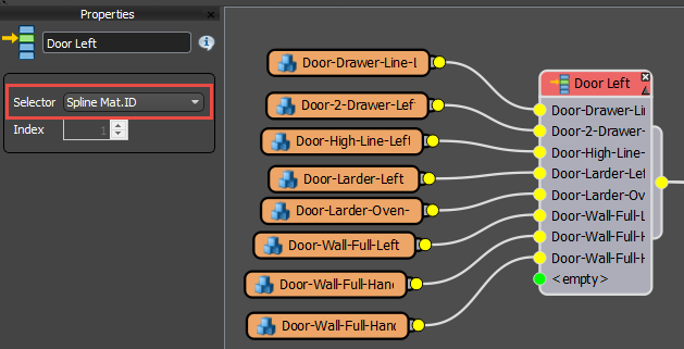
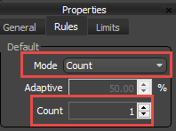
- To get started, duplicate the existing L1S generator and detach any existing segments from the inputs. Change the mode to Count and set the Count Value to 1. This is similar to Scale but works more reliably in this style for my tests.
![Kitchen Cabinets with RailClone-image2016-6-28 16:9:3.png]()
- First we'll build the door itself. As we've seen, these are created from 3 segments: left, right and default, The two sides should not scale but the middle will. We'll need to create a calculation that finds the size of the middle section based on the length of the spline minus the two sides of the door, the carcass and any padding. To do this we'll start with a Compose operator attached to the Default input. This let's us combine the 3 segments into one unit.
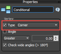
- Next create two Conditional Nodes and one Transform node. Wire one Conditional node to the first input of the Compose node, then the Transform node, and then finally the other Conditional node. The conditional nodes will be used to detect what type of vertex is used before the spline section. As we've seen this changes the side the door hangs. The transform node will be used to rescale the middle section.
- To do this, change for both Conditional node's, turn on Vertex > Type and set the Vertex Type drop-down to Corner.
![Kitchen Cabinets with RailClone-image2016-6-28 16:10:30.png]()
- Wire the Door Left selector operator to the first Conditional node's True Input.
- Wire the Door Left selector operator to the second Conditional node's false Input via a Mirror operator.
- Wire the Door Right selector operator to the second Conditional node's True Input.
- Wire the Door Right selector operator to the first Conditional node's False Input via a mirror operator. We have now set up some conditional that swap the geometry based on vertex type. Now let's scale the middle part of the door.
- Select the Transform node and export X Fixed Size . Wire the Door Default selector the the input.
- To calculate the size it's time for some maths. We need to take the length of the spline section and the deduct the size of the left side, the right side, the frame side, and any padding. Because we need to use the Padding and Frame size for another calculation in a second we'll create a sum for this separately. To do this, create an Arithmetic node and attach the Door Padding numeric node and the X Size of the frame/carcass sides (now you know why we exported it earlier!)
- Now export the X Size attribute for both the Left and Right selector nodes.
- Create another Arithmetic node and attach both X Size attributes and the arithmetic operator we just created. Change the operation to Expression and create the sum by opening the editor and entering XSectionLength-Input1-Input2-Input3. This give you the space left for the middle section of the door.
- Wire this arithmetic node to the transform node's X Fixed Size input.
- Now we need to create some padding to add gaps between the doors. To do this create another Transform operator and wire it to the generator's Start, End, and Corner inputs.
- We want the gap to be same size as the frame/carcass, plus any additional padding. We already created this equation earlier so we can now reuse it. Right click on the transform node and export X Fixed Size.
- Wire the existing padding and frame size arithmetic node to the newly exposed input and that's it. All we have to do now if make sure the doors are in the correct position. At the moment they are in the wrong place on the Z and Y axis.
- The Y axis is easy, we can just export the generator's Y Offset property and connect it to the Y Size numeric node. But let's add a bit more flexibility. We also want to be able to offset the doors from this position so they can appear either inside the frame or on the surface. To do this create yet another Arithmetic node and wire Y Size to the first input.
- Create another Numeric node, change the mode to Scene Units and call it Doors Offset. Wire this to the second input.
- Change the Arithmetic node's mode to Expression and enter -Input1+Input2
- Finally wire the Arithmetic node to the Y Offset input and the doors will be correctly placed!
- To fix the Z Offset you need the take the same value as used to place the Carcass/frame sides and add it to the padding value. Do this with another newArithmetic operator and wire the results to the Z Offset property. Nearly there! Only one more generator to go...
Creating Centred handles
Finally, what about the handles? For the sides that's not a problem because we've already added them to the door segments but for handles that are on the top or bottom, for example on drawers, we can't use this approach because they will scale incorrectly with the default segment. Instead.we use another generator and add them to the Evenly input with a count value of 1 to keep them centred.Here's how:
- Duplicate the Doors L1S Generator and remove the existing segments from the inputs.The Z and Y Offset are set correctly for this one already.
- You need to make sure that the spline is always broken on the corners. To do this, wire a null segment to the Corner input.
- Change the Evenly mode to Count and enter a Count Value of 1. As mentioned this will add one handle to the centre of each spline section. Remember, where no centred handle is required a null segment is selected instead.
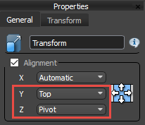
- Wire a transform operator to the Evenly input and wire the Handles selector to the Transform operator. Change Alignment > Y to Top and Alignment > Z to Pivot. This is to ensure they align correctly with the rest of the geometry but what we haven't done yet is allowed for the thickness of the door, so to do this export the Y Fixed Translation value.
![Kitchen Cabinets with RailClone-image2016-6-28 16:17:4.png]()
- Create a new Arithmetic node, set the mode to Expression and enter -Input1. Wire this to the Y Fixed Translation input.
- Finally right-click on the Door Default selector node and export the Y Size attribute. Wire this to the Arithmetic node to offset the handle the thickness of the door.
Conclusion

We've made it to the end! The graph looks complicated, but really it's just about connecting size of segments to automatically place geometry correctly. And though it might take a little time to build I think it's worth the effort. The same principles can easily be applied to all kinds of other uses and we now have a reusable style where you can select cupboards based on material ids, change the hanging direction of the doors using vertex types, control the overhang of the worktop and the depth of the plinth offset, change the width of the cupboards, choose door padding or even change the kitchen from framed to surface mounted, and choose whether or not to use a worktop. The calculations for all the segment size are based on the door segments you add so once it's created it's easy to change the geometry to get completely different results.
In fact even for beginners this style is helpful because you can swap the geometry without ever having to know how the rest of the graph works. Until next time, stay tuned for future tutorials including creating books and other objects to populate shelves, for more information about many aspects of RailClone's features please see our reference section or visit the tutorials page for more Tips&Tricks videos as well as in-depth tutorials.