Требования
- info RailClone Pro, Corona
Next time you’re in a city, examine the way modern buildings are constructed. What do you see? Repetition, and lots of it. A huge part of the built environment is constructed using repeated modular components. This makes modern architecture an ideal candidate for 3D modelling. Whole buildings can be created with just a few objects, and when combined with procedural modelling techniques, you can very quickly populate entire scenes in a way that’s easy to update and fast to iterate.
The RailClone plugin for 3ds Max is ideal for this kind of task. It allows you to define simple construction rules to generate one dimensional and two dimensional arrays using a node-based interface. Because RailClone automatically instances geometry and render time, the source meshes can contain a tremendous amount of detail with little impact on render times and memory consumption, even if the scene contains millions or even billions of polygons.
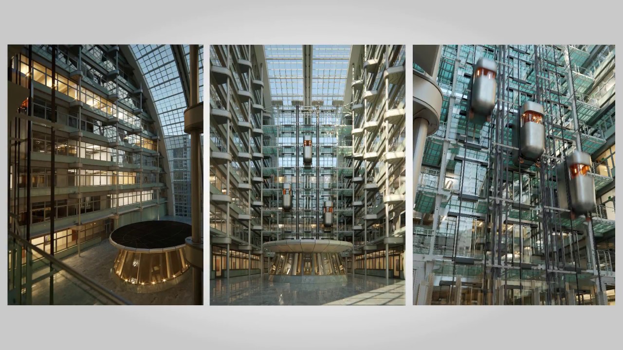
In this tutorial we’ll use a scene by Bertrand Benoit to explain how RailClone can be used to model architecture inspired by the Ludwig Erhard Haus, better known locally as Gürteltier (Armadillo) or Berlin’s chamber of commerce. We’ll examine techniques to make an almost entirely procedural modular atrium by creating glass facades, an elaborate elevator shaft, plus a skylight and tiled floor. Bertrand's scene is available for sale on Turbosquid.
Even though modular design exists all around us, an issue when reproducing it in CG is that repetition can start to make scenes look unrealistically perfect. To make the environment appear a little lived-in, we’ll finish up by examining how to randomise open windows and blinds in the windows as well as adding texture variations to the marble floor.
Block out the scene
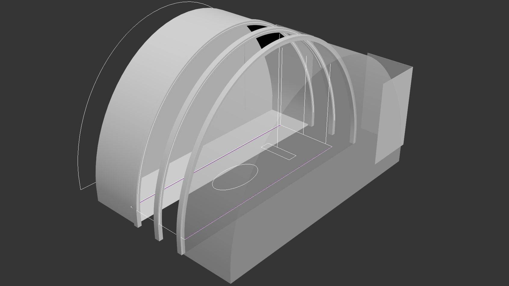
The majority of the scene is laid out parametrically. However, to be able to create the rest of the model, you should block in the major volumes and anything else that’s not repeated more than once. For everything else, create splines to define the paths for the major components that you can later use in RailClone. For example, create splines on the sides and end of the central atrium to describe the path of the facades, draw a vertical spline at one end to define the height of the elevators, make a closed spline that will be used to create the floor, and add several arched splines for the roof light.
Model and align the skylight geometry
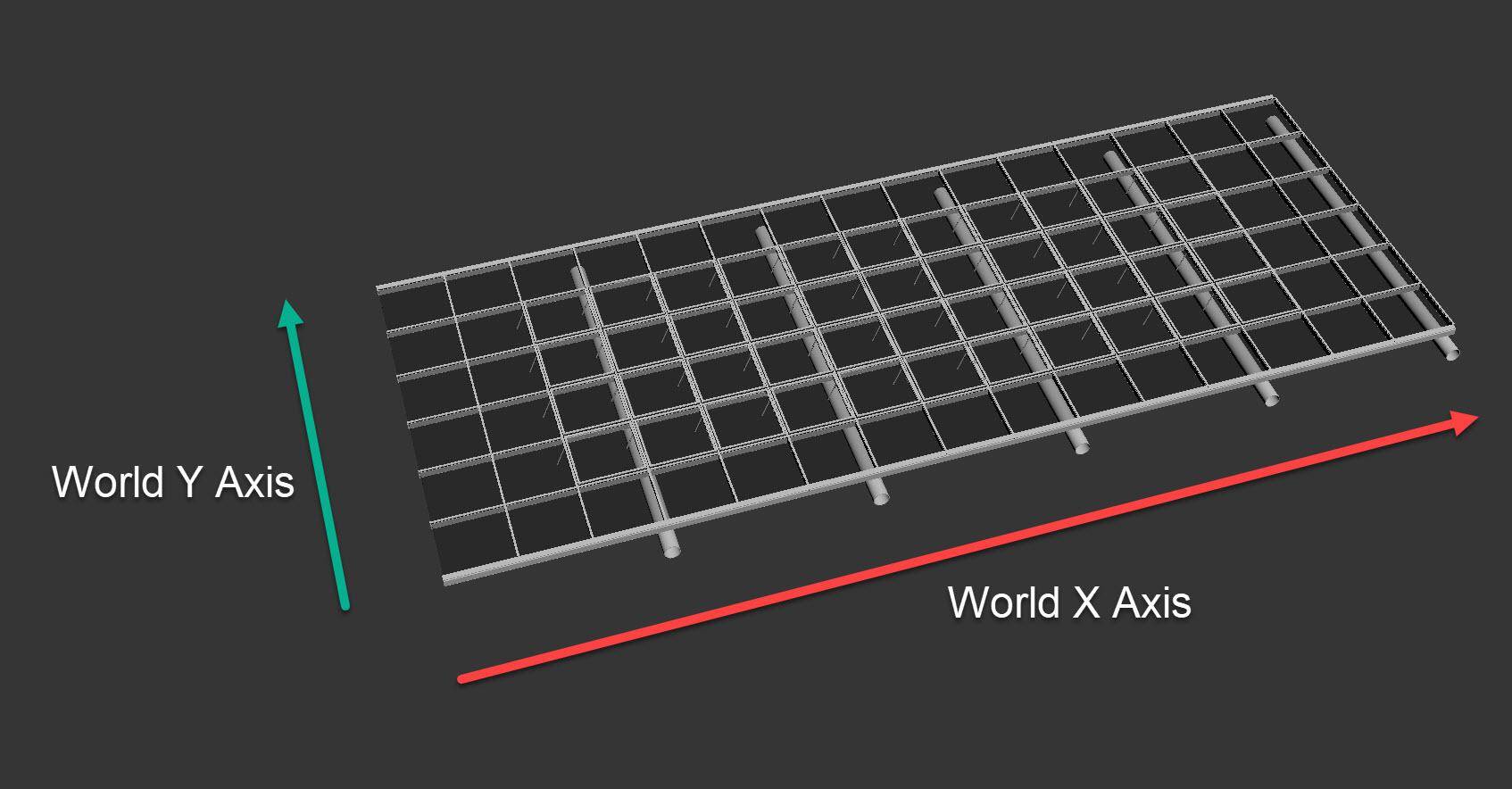
Model a tileable section of skylight geometry with sufficient detail to deform along a spline. The orientation of the pivots is important. The skylight object’s local X axis will be aligned with the direction of the path and its Z axis aligns to the RailClone Object’s local Z axis. The easiest way to ensure that the orientation is correct is to align the object imagining that the spline’s path is along the World X axis. Position the pivot to the bottom of the glazing bars and then use the Reset XForm utility to align the pivots to world space. All the other geometry is oriented in the same way.
Understanding the L1S Generator
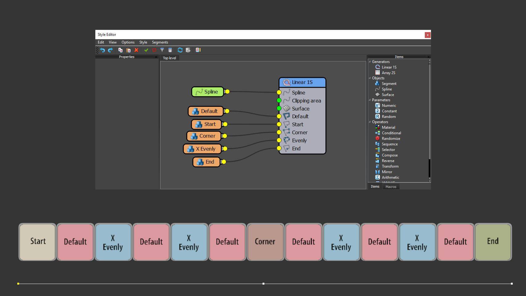
RailClone has two types of array - called Generators - that can be used to create procedural models. The simplest of these is the L1S Generator, a one-dimensional array that enables you to duplicate and deform geometry (called Segments) along one or more splines. You can target five separate parts of the array with different Segments: at the start, end, corners (defined by vertices), evenly spaced intervals along the spline, and finally a default Segment that fills in any remaining gaps. We’ll use this type of Generator to add the skylight, lifts and awnings.
Create the skylight
Create a new RailClone object and open the style editor. Add an L1S Generator and wire a Spline node to the Generator’s Spline input. From the Properties panel, pick the spline from the scene that is used to define the path of the skylight. Create a Segment node, use it to load the skylight geometry from the scene and wire the node to the Generator’s Default input. Because the path is to the side of the aperture, we need to change Properties > Alignment > Y to Top, then change Z Axis to Pivot to align the bottom of the glazing bars with the spline. Close up the gap between Segments caused by the horizontal pipe by reducing the Right Padding value.
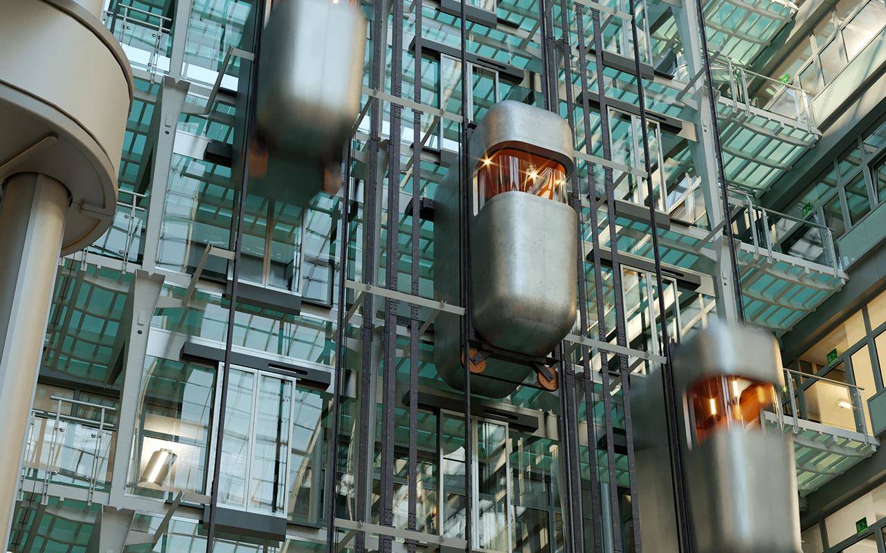
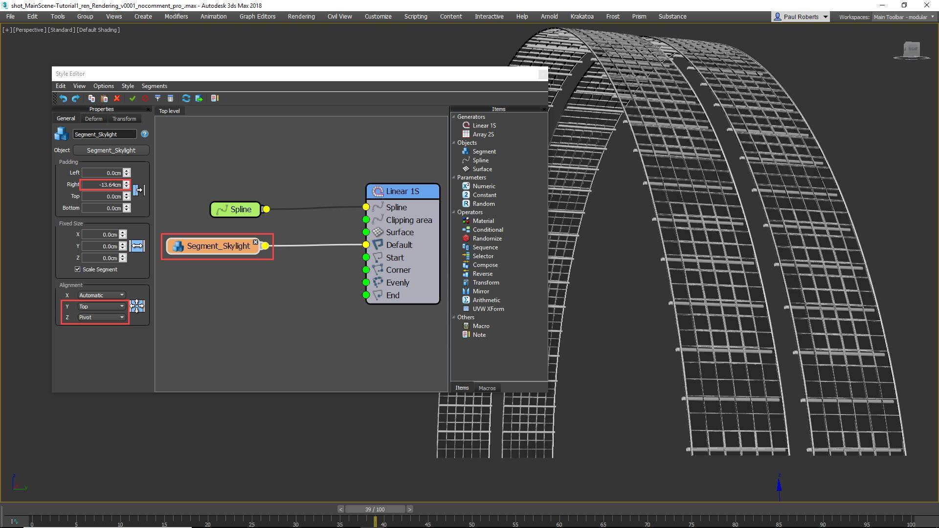
Create the Elevator
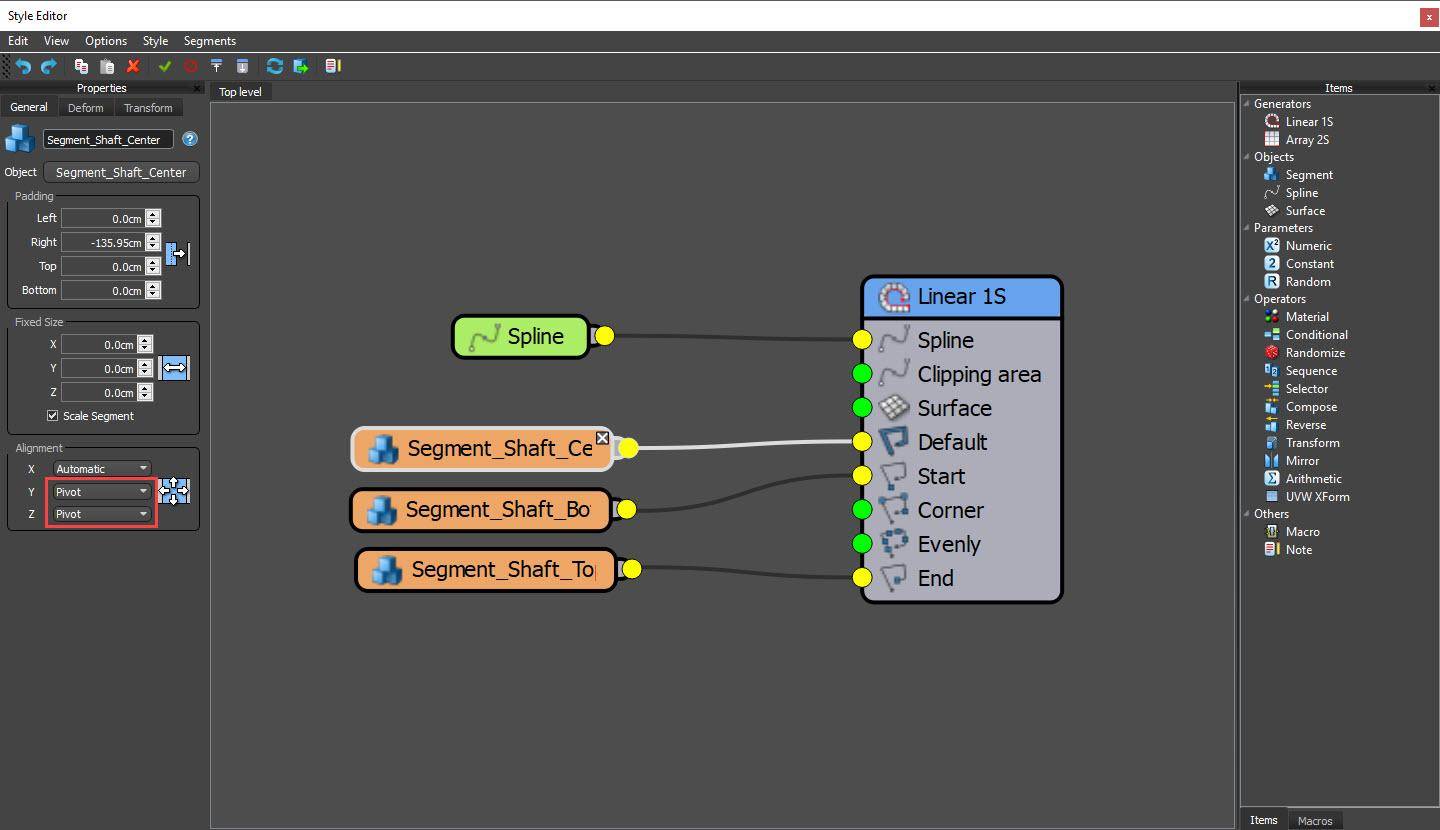
The elevator shaft also uses a one-dimensional array, but consists of 3 different Segments. Create another RailClone object and add an L1S Generator. Attach a Spline node and choose the elevator spline from the scene. Create a Segment node and pick the bottom elevator geometry. Disable Slice and wire it to the Start input. Set the Segment’s Y and Z alignment property to Pivot. Add the top of the shaft by copying and pasting the existing Segment node and swapping the geometry for the top elevator object. Wire this to the End input. To fill in between, clone the Segment node a third time. Swap the geometry for the centre elevator object and wire the node to the Default input.
Overlap Segments with Padding
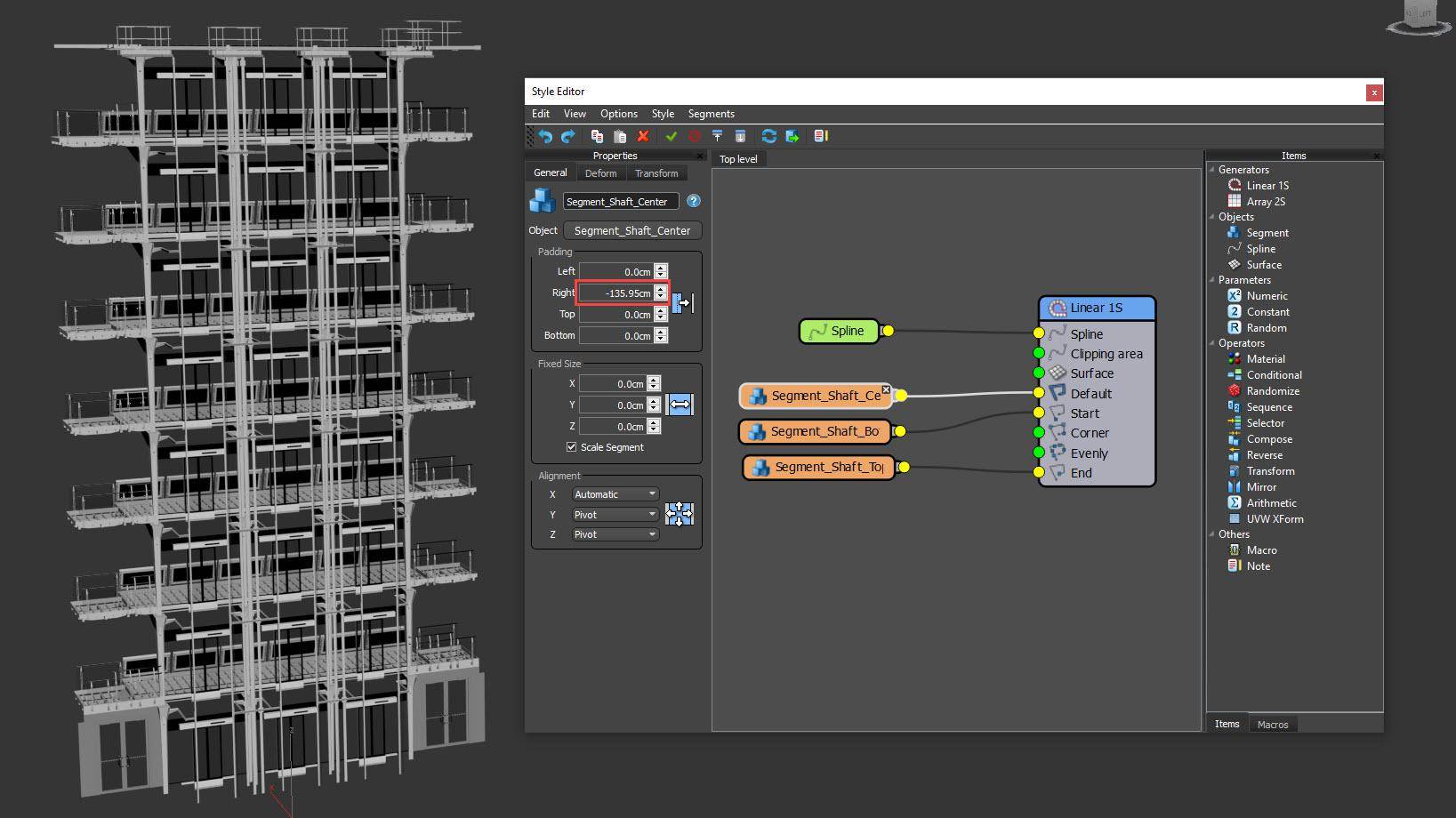
RailClone uses the geometry’s bounding box to position adjacent Segments. This is why the railings are preventing the Segments for the elevator from jigsawing together correctly. To fix these, it’s necessary to overlap them using the Padding property found in the Segment node’s General tab. Reduce the Right Padding value for the Segments in the Default and Start inputs until the elevator door aligns with the floor below correctly, and the elevator is finished. If necessary, you can adjust the length of the spline to change the height of the shaft and refine the overlap for the final Segment. The L1S Generator is also used in this scene for the awnings and a structure between the skylights.
Understanding the A2S Generator
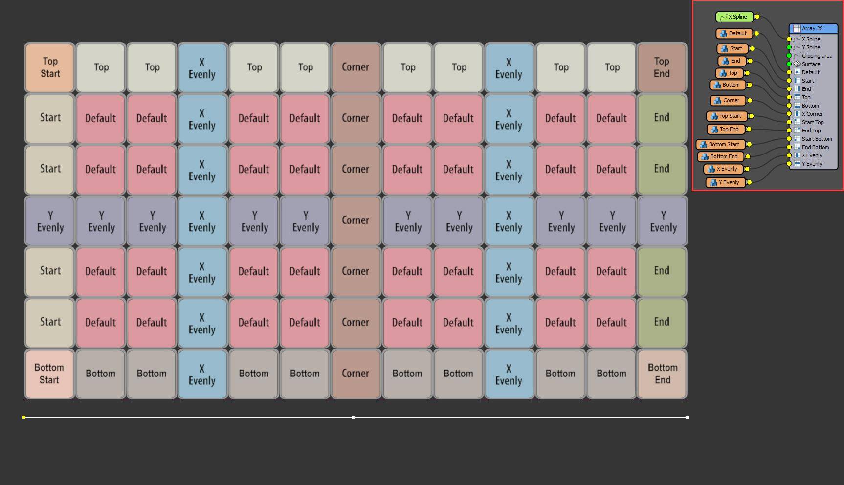
The second type of Generator is for creating two-dimensional arrays. It’s much more advanced than the Generator used in the previous steps, but it’s easiest to think of it as a stack of L1S Generators. You can target twelve different parts of the array with different Segments: the start, end, corners (defined by vertices), top, bottom, top and bottom left and right, at evenly spaced intervals along the X axis and Y axis, and finally a default Segment that fills in any remaining gaps. We’ll use this type of Generator to add the floor and facades.
Aligning geometry for A2S Arrays
The A2S generator’s 2D arrays are built on the X and Y axis. Consequently, source geometry should be orientated to these axes. For vertical styles including facades this can cause confusion, but overall, source geometry should be aligned as if it is laid flat on the ground.
Create the floor tiles
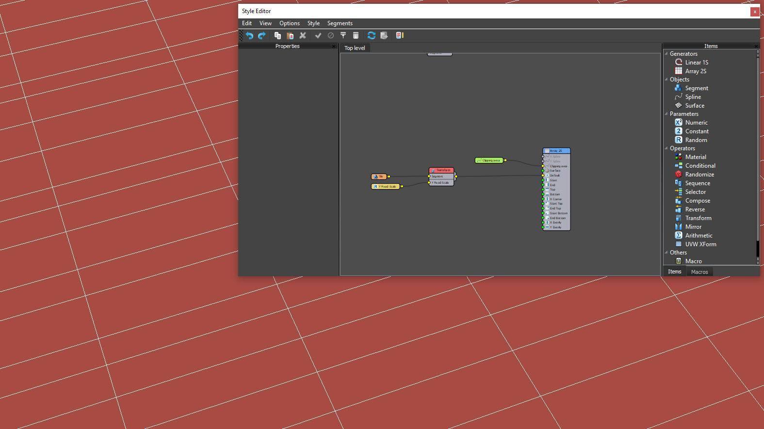
The floor tiles are created using an A2S Generator that automatically fills an area defined using a closed spline. Create a new RailClone object, open the style editor and add an A2S Generator. Wire a new Spline node to the Generator’s Clipping Spline input and pick the floor spline from the scene. In the Generator’s properties enable Extend X/Y Size to Area. Create a Segment and add tile geometry. Wire this to a new Transform node and export Y Fixed Scale. Attach a new Random parameter node to the Y Scale input and set the mode to Array Y Row so that each row has a different height. Finally, set the minimum value to 40% and leave the Maximum at 100%.
Randomly offset rows
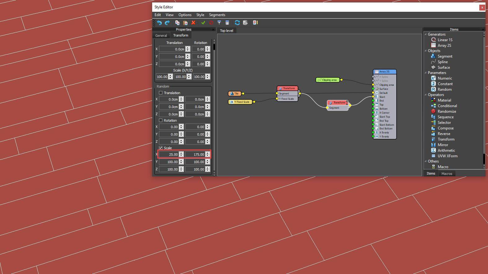
To randomly offset each row we will randomise the X Scale to the first tile. To do this, add a new Transform operator and wire it to the Generator’s Start input. Connect the existing Transform node to the new node’s input. Open the Properties and go to the Transform tab. Enable Random Scale and set X Minimum to 25% and X Maximum to 175%. To complete the style, we will add some grout between the tiles. For this, we need to learn how alternate between two Segments using Sequence operators which can be used to create patterns on the X or Y axis.
Add grout to the tiles
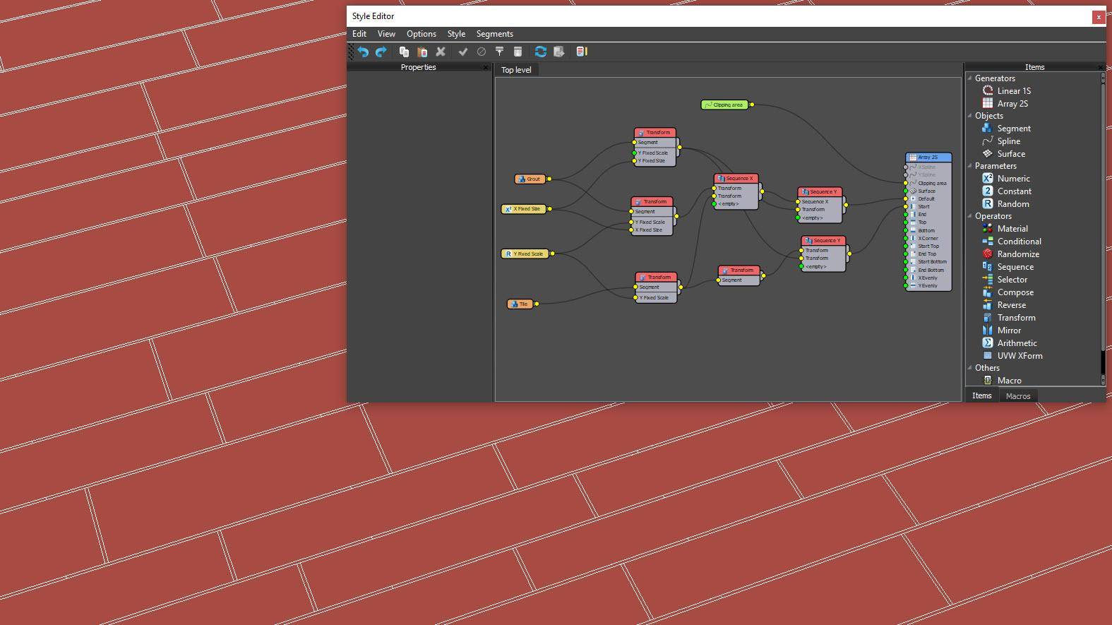
Create a new Segment and add grout geometry. Connect it to two new Transform operators. For the first, export Y Size, and for the second export both X Size and Y Fixed Scale. Wire the existing Random Number node to the latter’s Y Size input and wire a new Numeric node to the X Size Input. This will be used to edit the thickness of the grout. Insert a Sequence operator to the Default input and wire the Transform node to its first input. Wire the tile to the second input to create a repeating pattern on the X-axis. Now insert a second Sequence operator to the Default input, change the Increment at Setting to Y and attach the other Transform operator wiring the Numeric node to its Y size input. Repeat the last step for the Start input.
Randomise floor textures
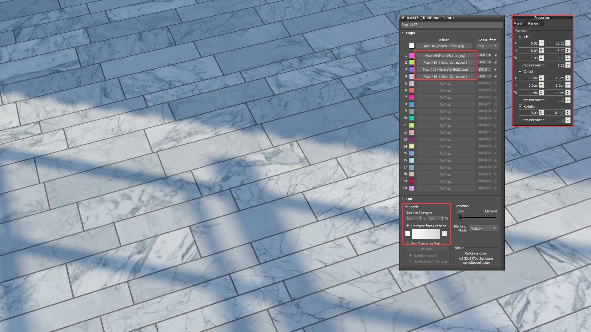
RailClone can automatically apply UVWs to Segments by enabling Apply Box mapping in the Deform tab and entering Length, Width and Height dimensions. To create a more realistic floor we can randomise the tiling and rotation of the UVWs to create nearly limitless variations. To do this, wire a UVW XForm operator after the tile Segment and enable Random Tile. Set U and V Minimum to 8 and Maximum to 15. Turn on Rotation and set the Maximum to 360. For more variety, use a RailClone colour map to randomise between bitmaps and even add a random tint.
Add the facade to the ground floor
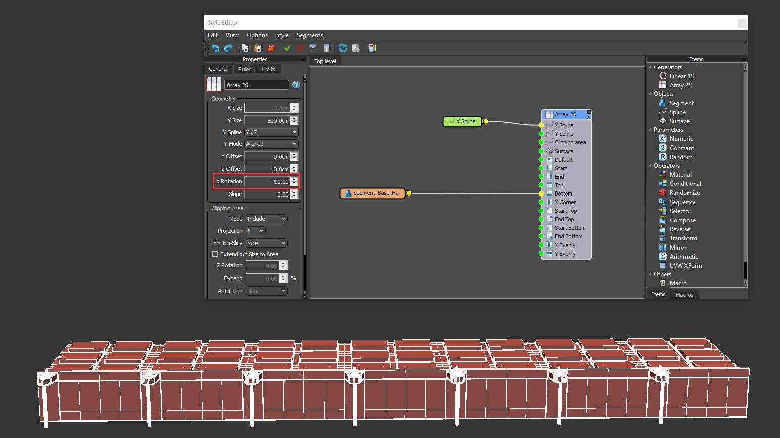
To create the facade, add a new RailClone object and an A2S Generator. Attach a Spline node to the X Spline Input and use a spline the length of the atrium. To set the Y Size of the array, use the Generator’s Size value. Now, to add the ground floor, create a Segment, pick the base geometry with the unglazed wall, and then wire it to the Bottom input. Change alignment for all axes to Pivot and turn off Slice. At this point, the array is created on the X/Y plane. To rotate it so that the facade is vertical, change the Generator’s X Rotation value to 90.
Add the default and top floors
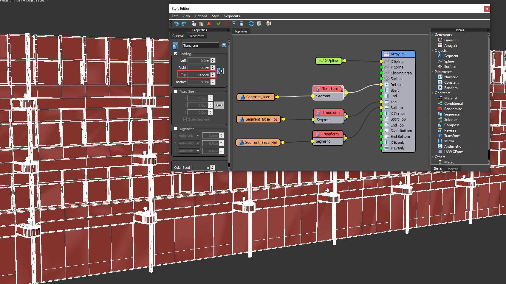
To add the other floors, clone the existing Segment and pick the geometry to be used for the bulk of the facade. Wire it to the default input. As we saw with the elevator earlier, there is geometry preventing the Segments jigsawing together correctly. Fix this by adding transform operators to both Segments and adjusting the Top Padding values until they lock together correctly. Do the same thing for the top floor but note that the overlap is also dependent on the Y Size of the array.
Add facade variations
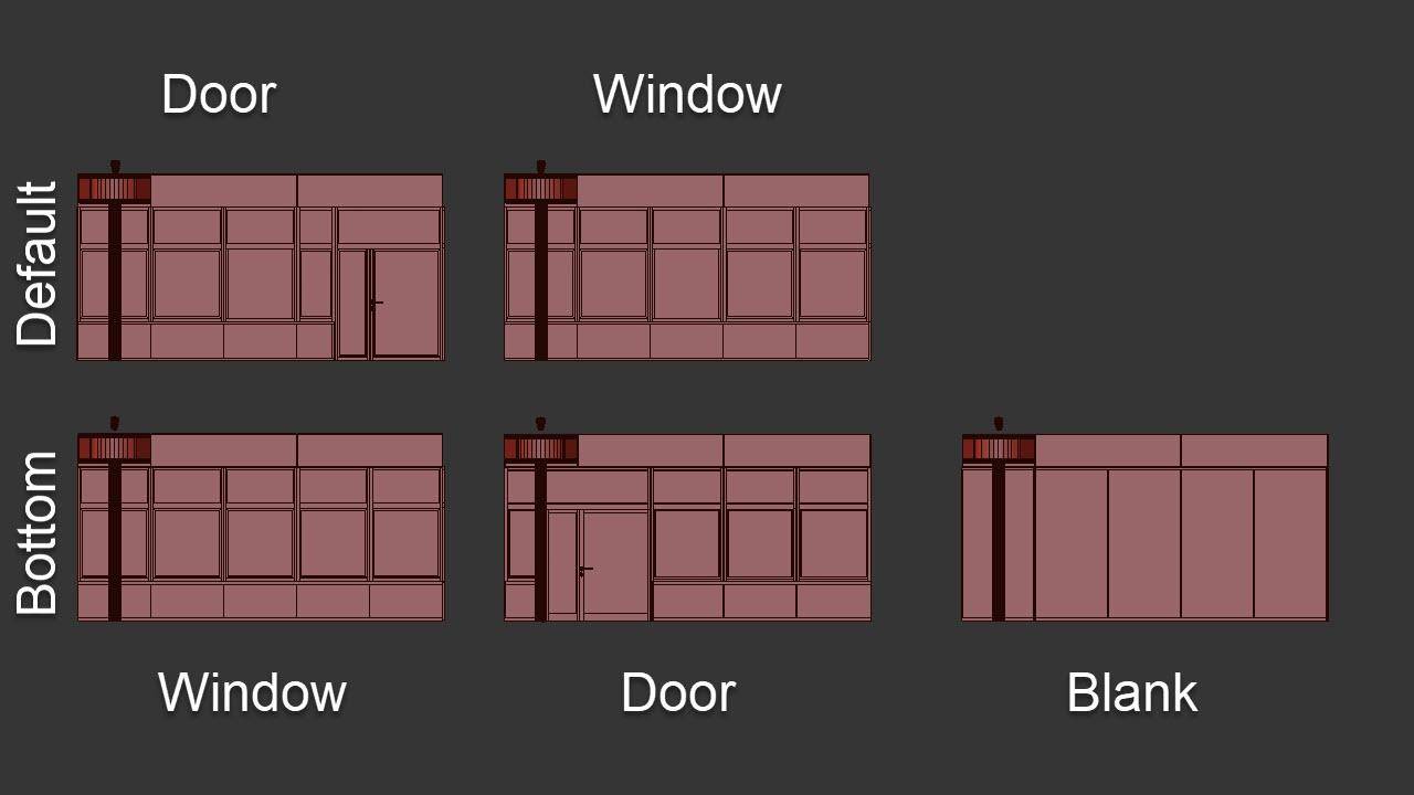
There are actually three facade models for the ground floor: a blank section, one with an open window and another with a door. For the main facade, a section with a window is used apart from where the elevator meets the facade, where a section with a door is needed. We can easily control how these are placed using Spline IDs. To set this up, wire Selector operators after the existing Default and Bottom Segments. Change the selector node’s mode to Spine Mat. ID. Duplicate one of the existing Segments as many times as necessary to import the other facade Segments.
Add the Segment variations
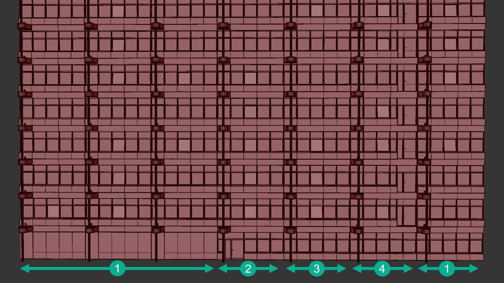
Wire the default Segment with the window to the first three inputs of the Selector operator and wire the door Segment to the fourth. This means that using spline ID 1 to 3 will create a window and ID 4 will create a door. Do something similar for the Bottom input so that Spline ID 1 creates a blank wall, 2 creates a door, 3 and 4 both create windows. Set the Generator’s Bevel Mode to None and you can now refine and edit Material IDs on the spline to control the choice of Segments.
Randomise window angles
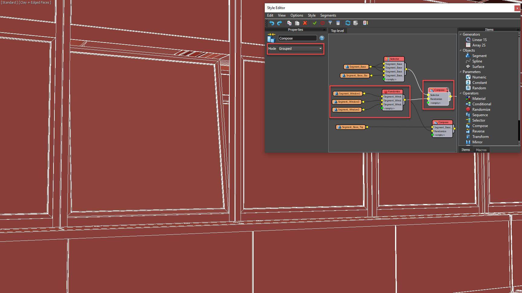
To add some subtle variety, we can randomise the amount each window is open. To do this, there are 3 windows in the scene at different angles. Their pivots are positioned so that when aligned with the facade geometry they’re already in the right place. To add them to the graph, import them into new Segments and wire them to a Randomise operator. To combine them with the windows, insert a new Compose operator after the Selector in the Default input and the Segment in the Top input. Change the Mode to Grouped. Wire the Random operator to the Selector node’s second inputs.
Compose operator modes
The compose operator is used to combine multiple segments so that RailClone processes them as though they are one. It has two modes: Sequential mode places items one after another along the path and Grouped mode aligns all of the geometry to the pivot point of the segment wired to the first input.
Add randomised blinds
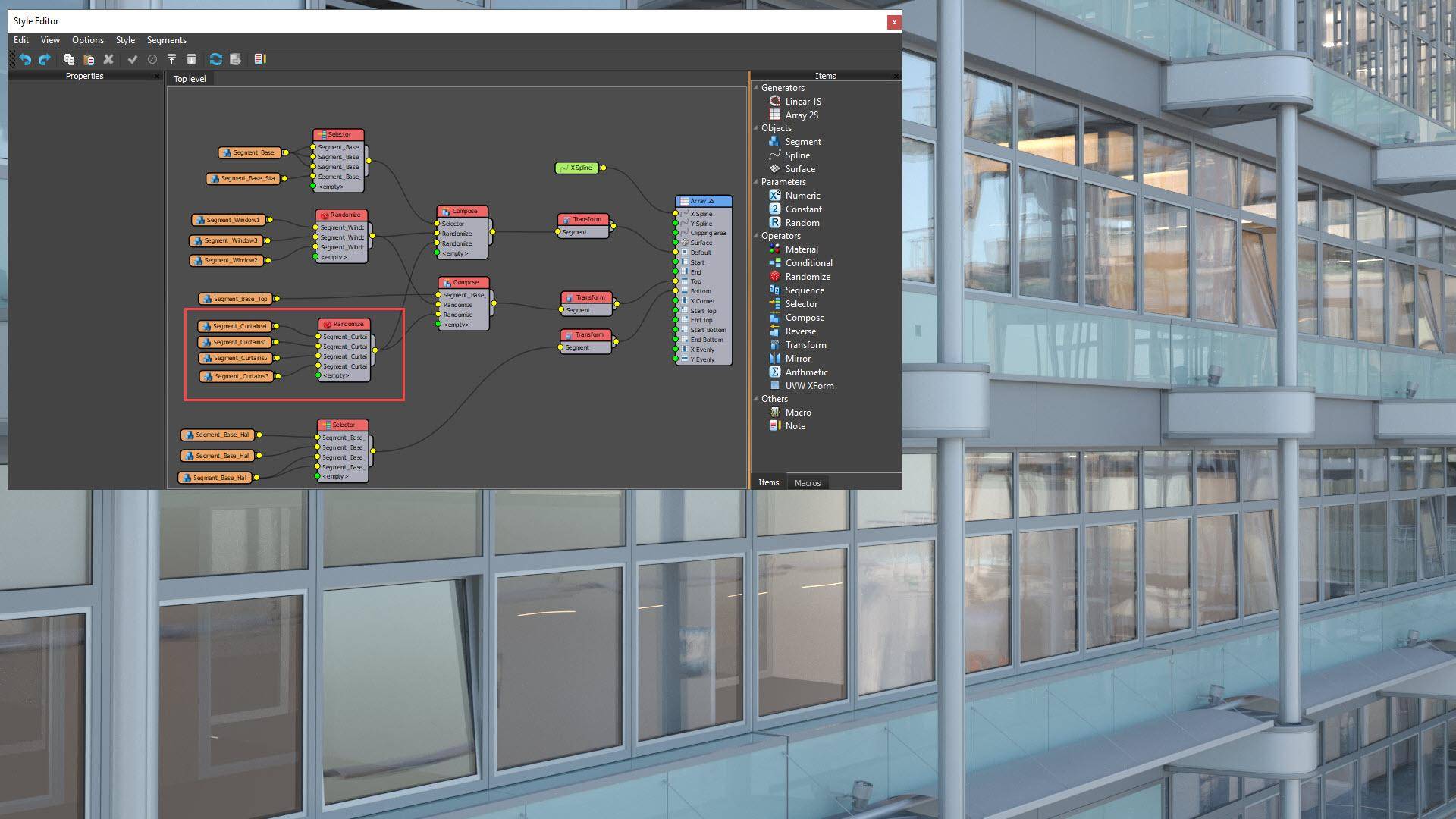
Random blinds or curtains can be added using exactly the same technique. There are 4 blind configurations which should be loaded into new Segment nodes. Wire these to a new Randomise node and wire the Randomise node to the 3rd input of the existing Compose operators. Each facade section now has a window with a random angle and one of four possible blind layouts. These additions can really help to break up the repetition of the modular architecture and bring the environment to life.
Use booleans to clip the facade
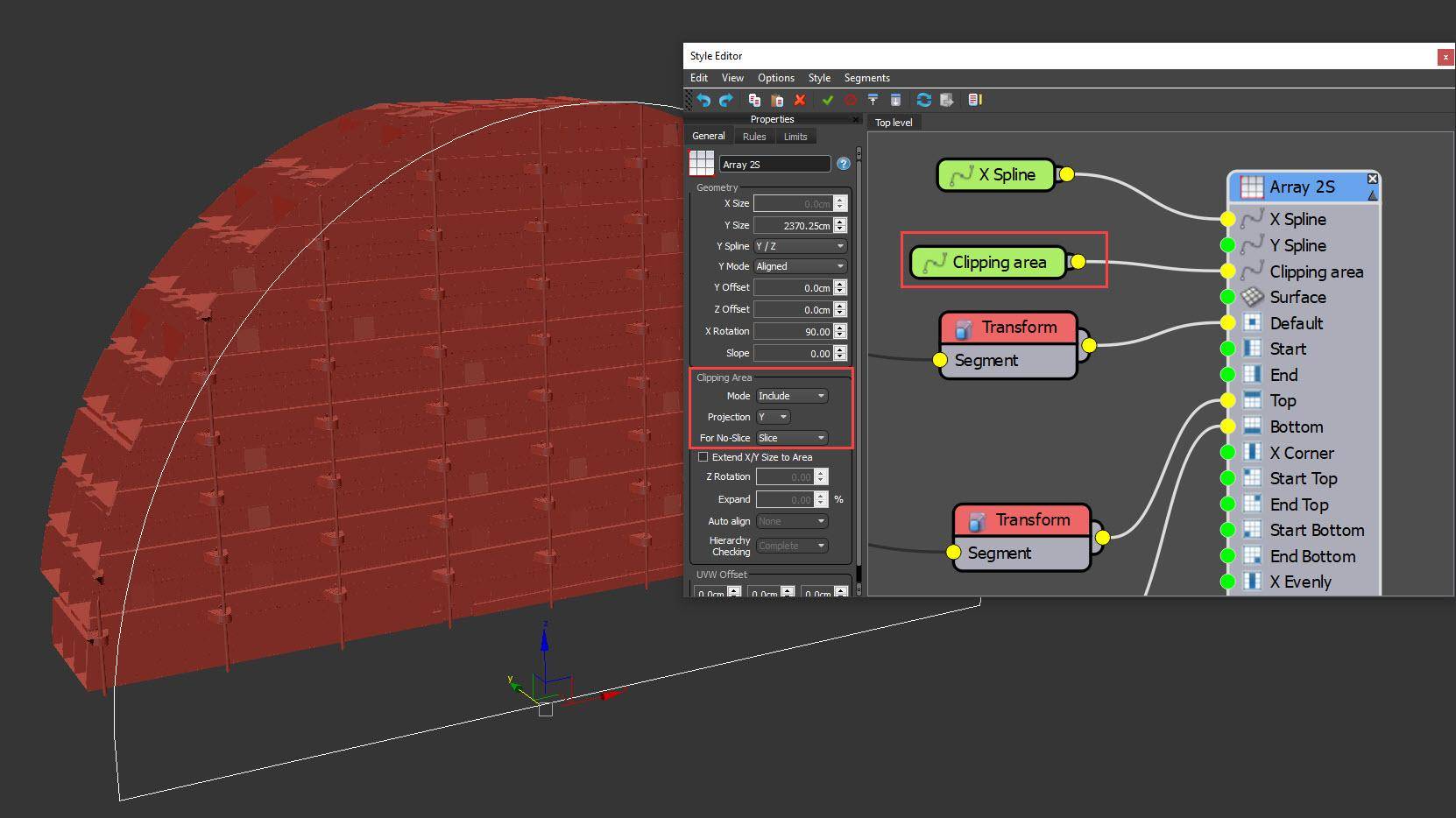
The final step is to trim the facade to the curvature of the roof. For this, we use RailClone’s boolean Clipping feature. Create a closed spline that outlines the shape of the building’s section. Add this using a Spline node to the RailClone graph and wire it to the Clipping Spline input. In the Generator’s properties, change the Clipping Area mode to Include and projection to Y. At the beginning of this tutorial we disabled slicing so now we must change the For No Slice option to Slice. This will force slicing the geometry by the clipping path only. That’s the modelling complete! All that remains is to duplicate this object to create the other side of the atrium.
Mirror Arrays
To create the other side of the atrium, you can duplicate the existing RailClone object and its spline, then mirror the geometry. The L1S generator has a simple property for this, but for A2S generators you will need to add Mirror operators to all the geometry inputs.