A few weeks ago we announced the release of RailClone 4.3. At the time we focussed on support for the freshly released 3ds Max 2022, but what we didn’t mention was that RailClone 4.3 also includes some handy improvements that make it even faster and more versatile. In this post, we’d like to share a little more about these latest changes.
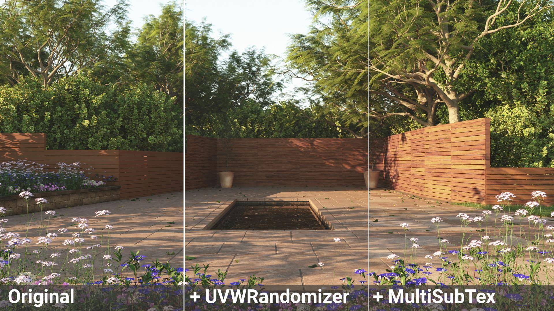
For a start, V-Ray users can now use the VRayMultiSubTex and VRayUVWRandomiser maps with RailClone. Just by enabling Instance ID Mode, you are now able to randomly scale, offset, and rotate the UVWs for each segment. You can also randomly assign bitmaps, including the ability to randomise their hue, luminosity, and gamma. These two maps together are tremendously handy for adding a lot of variation to your parametric models. Of course, much of this was already available using the UVW XForm node in RailClone along with RailClone Color, and we’re happy to report that the latter is also now supported by V-Ray 5 GPU.
RailClone users who create complex styles with a lot of nodes will find their RailClone objects evaluate much quicker in this release. Several of our most sophisticated assets enjoyed a speed boost of up to five hundred percent!
Perhaps the biggest change to affect the way you might build your styles in the future comes in the form of a new Deform tab added to the Transform operator. The new tab incorporates all of the Deform settings found in the Segment node, but with a key difference - you can now easily change the these settings for multiple segments in one go. Much simpler!
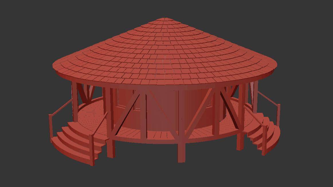
The new Deform settings also have another function. Imagine that you're using RailClone to make a circular glamping pod like the one shown in the preview below. In order for a style like this to be created correctly, the segments need to be able to bend around a circular spline. For this to work, Bend > Deform needs to be enabled.
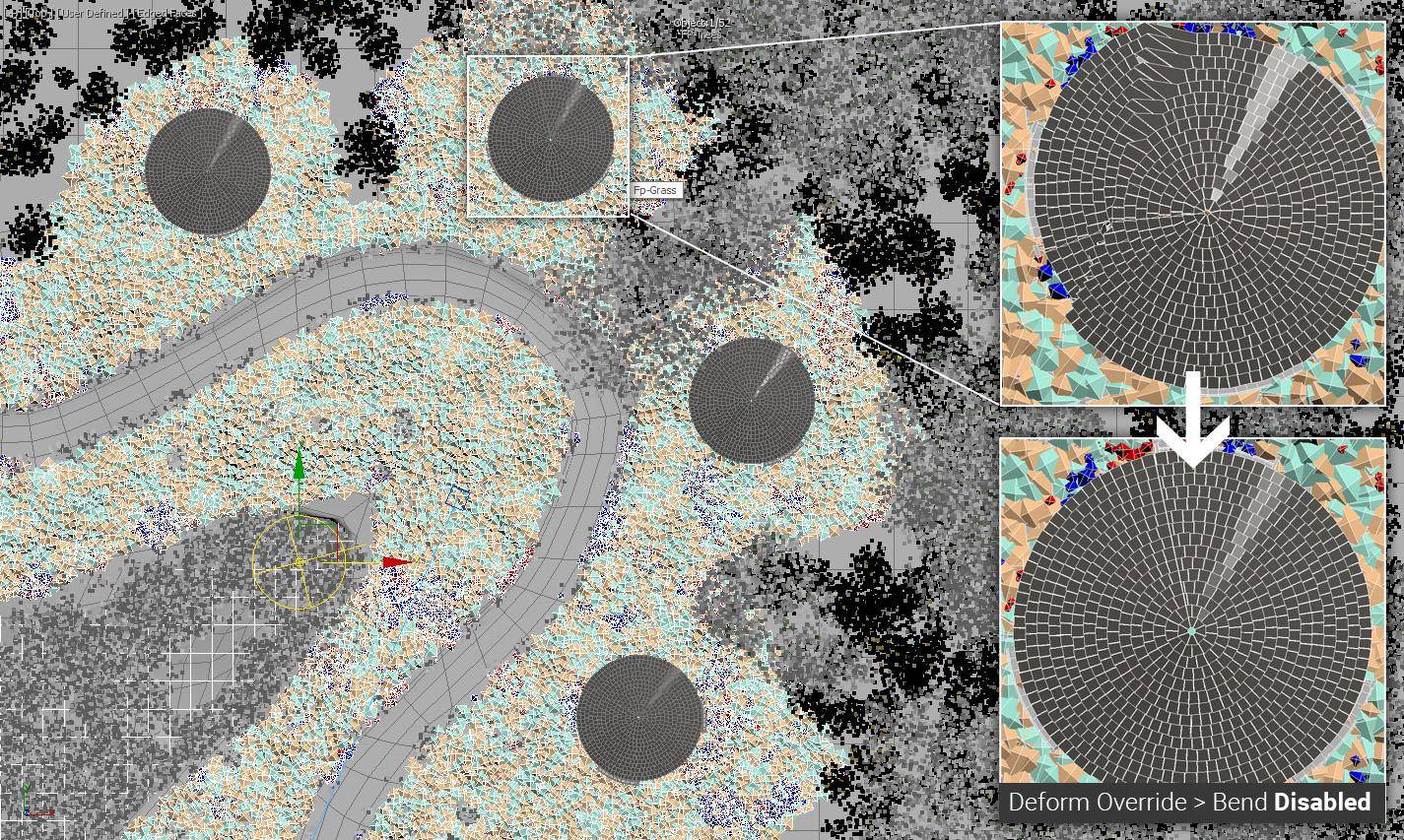
Now let’s say we want to nest the generators we used to make this pod inside another linear array, and then distribute several pods along a curved path. Because Bend was enabled, each pod will deform to follow the path, which isn't at all what we want. What can we do? In previous versions of RailClone, there simply wasn’t a solution that would allow this in a single style, but from RailClone 4.3 and onwards, you can now add a Transform node after the nested generators and override the Deform settings. The segments will still deform around the circle to create a single pod, but after that, no further deformation will take place. We hope this will open up many more opportunities when using nested generators in RailClone.
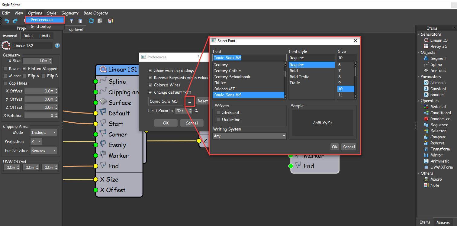
If you’ve already upgraded to RailClone 4.3, you might have noticed that the style editor has had a subtle facelift to bring it in line with Max’s Darker UI and harmonise with the recent Forest Pack 7 release. What you may not have spotted is a new option to customise the font and text size. To access these new settings, open the style editor and go to Options > Preferences. Enable Change Default Font and click the ellipsis to change the typeface and size. Go on, we know you want to switch it to Comic Sans!
Finally, we've added several new Macros for this release. A few of these have cropped up in previous tutorials but are now a part of the core application, but many are completely new. From the tutorials, there are now 5 floor generators that require just 3 nodes and can extract multiple plank textures from a single map, plus there’s also an unusual macro for creating phyllotactic spirals. New macros include a whole raft of new Logic nodes which when combined with the new Array Attribute nodes gives users easier access to some low-level parameters without needing to use or understand the Expressions editor. There’s also a node for calculating the distance between the X-spline and a surface that’s great for bridges and boardwalks, plus a node that enables adaptive scaling for the Y-axis. You can read more about these nodes and their parameters below. These Macros are also available for RailClone Lite making the free version even more capable.
If you’re ready to update, RailClone 4.3 is out now. To get it, visit the My Products section of your User Panel.
If you're not yet a RailClone user, we'd like to remind you that we have a free Lite version available that has many of the features of the Pro edition, never expires and can be used commercially. You can download it from the RailClone product page.
And finally, in addition to these point releases, you can expect more news related to RailClone assets very soon, plus a major new version of RailClone expected later this year. Stay tuned for more information!
Latest Macros
Many new macros are included with this release. Below you'll find descriptions as well as information about their inputs and parameters to help you start to use them for your work. Several of the more advanced macros will soon be featured in dedicated videos as part of an upcoming Macros Monday series of tutorials.
Transform > Surface to Spline distance
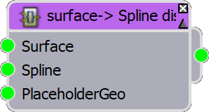
The Surface->Spline Distance node is able to calculate the distance between the X spline and a surface. It outputs a simple measurement in scene units making the node flexible enough to be used for a wide variety of applications, however, it's particularly useful for setting the size of segments or nested generators to span the gap between the spline and a terrain. In the following example, the macro is used to set the X Size of a nested generator that's being used to create supports underneath a boardwalk.
To use the Macro, attach the same Surface and X Spline used in the final generator to its inputs. You'll also need to attach a placeholder segment that uses real geometry (usually a box or something simple, but it can't be an empty segment). The placeholder geometry isn't visible in the final style, but it's necessary to be able to calculate the distance correctly. Finally, the final generator in the chain to which it's attached must be named Linear_1S1 (this name is hard-coded into an expression used in the macro - but if you're happy editing macros it can easily be changed).
Transform > Y Adaptive
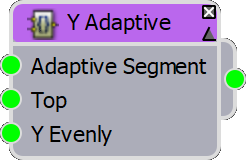
One of the most useful ways to distribute default segments is Adaptive mode. It works by calculating how many segments are needed to fill the array, and then subtly scales them so that they fit exactly without being sliced. This is great for ensuring that geometry isn't cut unintentionally and can dramatically help optimise your styles because scaled segments can be instanced. whereas sliced segments cannot. At the moment though, RailClone only supports this feature on the X-Axis of 2-dimensional arrays.
That's where this Macro helps out, it's able to create an Adaptive effect on the Y-axis. To use it, wire your segment(s) to the Adaptive input and then wire the Macro to the generator in the usual way. If you're using segments in the Generator's Top or Y Evenly inputs then you should wire these to the macro as well.
Generators > Bricks and Walls > Perforated
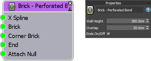
A new addition to our brick wall macros, this node can create perforated brick walls with parameters to control height, the overlaps of the bricks, and more.
Inputs
X Spline Sets the path for the wall. Corners work best at 90 degrees and vertices should be set to Corner, or Bezier Corner to work correctly.
Brick Attach a full-size brick segment. Make sure that Deform > Bend is turned off. You can also disable slice if you want to maximise instancing.
Corner Brick Attach a full-size brick segment. Often the same as the Brick input.
End Attach a partial size brick segment. This will be used in the gaps at the start and end.
Attach Null Attach a segment with no geometry. Required by the macro for calculations.
Properties
Wall Height Controls the height of the wall in scene units.
Overlap Controls the amount that bricks overlap.
Ends On/Off Enabled or disables the partial bricks on the ends of the wall.
Generator > Floors
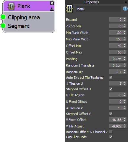
This category contains 5 new macros that use just 3 nodes to generate common parquet floor styles. As well as parameters to control the size of planks, this preset also has a handy extra feature - using the Auto-Extract Tile textures mode it can manipulate a segment's UVW mapping to randomise individual plank textures from a single map. It's really handy for quickly setting up materials when maps contain multiple planks or are based on a veneer. You can watch the tutorial that this macro is based upon below.
Inputs
Clipping Area Attach a spline to define the perimeter of the floor area.
Segment Attach plank geometry. To use the Auto Extract Tile Textures feature, the source geometry should be correctly mapped. The easiest way is to apply a UVW Modifier, change the mode to Box Map and fit the gizmo to match the dimensions of the plank.
Properties
Expand Increase this value if you have missing boards around the perimeter of the area.
Z Rotation Rotates the entire floor to change the direction of the planks.
Min Plank Width Sets the minimum random width of the plank.
Max Plank Width Sets the maximum random width of the plank.
Offset Min Sets the minimum random offset to stagger boards. The value is a percentage of the board's length
Offset Max Sets the maximum random offset to stagger boards.
Padding The size of the gap between boards.
Random Z Translate Randomly adds some offset on the Z-axis to make the construction of the floor look more realistic.
Random Tilt Randomly tilts boards to create unevenness. Small subtle values work best.
Auto Extract Tile Textures When enabled, the board's UVWs are edited to extract plank textures from a single bitmap. The following parameters control this effect.
# Tiles on U/V Sets the number of tiles in the bitmap on the U/V axis.
Stepped Offset U/V Enables stepped offset on the U and/or V axes.
U/V Tile Adjust Used to scale or contract slightly the UVWs. Useful if you need to clip out grout or joints.
U/V Fixed Offset Used to offset the UVW mapping. Often used following a U/V tile adjust to further remove grout or joints.
Random Offset UV Channel 2 Shrinks the UVW hulls to a pinprick and scatters them around UV space 0-1. Can be used to randomly extract a colour or value from a map without needing a specialised shader. Useful for exporting to games engines or for renderers that don't support RailClone Colour.
Cap Sliced Ends When enabled, sliced ends of planks are capped.
Generators > Tiles > Random Tiles
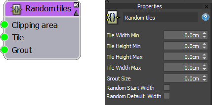
Creates tiles that can be randomly scaled on the X-axis per tile, and/or on the Y-axis per row. This macro also has the ability to add grout.
Inputs
Clipping Area Attach a spline to define the perimeter of the floor area.
Tile Attach a segment for your tiles. If you have multiple tile meshes, you can wire them through a Random or Sequence operator.
Grout Attach a segment for your grout.
Properties
Tile Width Min Sets the minimum randomizable width for tiles.
Tile Height Min Sets the maximum randomizable width for tiles.
Tile Height Max Sets the minimum randomizable height for rows.
Tile Width Max Sets the maximum randomizable height for tiles.
Grout Size Sets the size of the grout. Should not be left at zero.
Random Start Width When enabled, only the first tile's width is randomised. This creates an offset between rows but the tiles remain the same width.
Random Default Width When enabled, all tiles have a randomised width.
Logic
A new collection of Logic nodes is now included with RailClone. These are specifically designed for those users that want to do more with RailClone, but don't want to deal with expressions.
The Logic nodes are split into 3 categories. The Array Attributes nodes expose more or less all of the attributes that you'll find in the Expressions editor, without needing to write a single line of code. The Logic > Conditional nodes allow you to return a true or false value based on comparative tests. By using these in combination with the Attributes nodes you can create conditional relationships that are far more comprehensive than is currently possible with the vanilla Conditional operator. If you need to test for multiple conditions to determine if something is true or false, then we have added Gates which allow you to perform boolean checks like AND. OR, and NOT as well as some that are less common. Finally, we have switches that allow you to choose a segment or output a numerical value for use in your styles. Read on to learn more about these new nodes.
Logic > Array Attributes
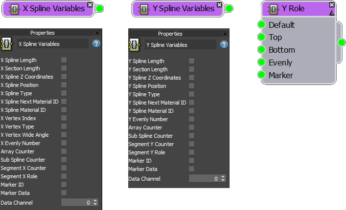
There are three Array Attribute nodes. X Spline Variables and Y Spline Variables are similar in that they allow you to export any attribute of the Splines wired to a generator. These can be used with other logic nodes and with any other exportable parameter in your style. To output the value of an attribute, just activate its checkbox, but be aware that only one attribute can be selected at a time.
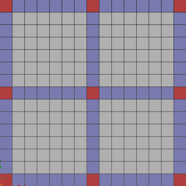
The Y Role node works differently. This node acts as a geometry switch that can be wired to the Start. End, X Evenly, X Marker or X Corner inputs of an A2S array. You can think of it as way of adding several additional inputs to a generator. For example, you can use it to add a segment where the Evenly rows and columns intersect. You could also use it to add different geometry where any of the following inputs intersect: Evenly, Marker, Corner, Top, Bottom. Start or End. In the illustration below - the read squares illustrate just a few of the new parts of an A2S array that can be targeted with this node.
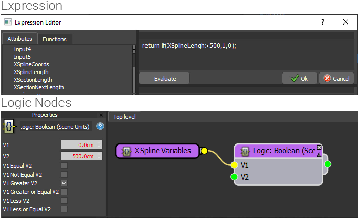
Logic > Conditional
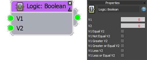
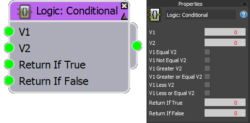
There are two nodes, but both test if two values are either greater, less, equal or not equal to one another. The Boolean version outputs a simple True or False value ( 0 or 1) that is typically used in conjunction with a Switch to choose between two values or segments. These nodes can also be used with Gates to test for multiple conditions or wired to the On/Off parameter of any node to turn on or off parts of a style.
The Logic > Conditional nodes are slightly different because instead of a true or false, they're able to output a configurable value. In some cases, this node can save a little time and space in your graph because it prevents having to use an additional Switch node.
For both nodes, only one checkbox should be selected.
Logic > Gates

The Gate nodes allow you to test 2 or more different conditions. The inputs are expecting a True or False value which is typically provided by a Logic > Conditional node, but could also be a simple Numeric or Constant Node set to Boolean. These nodes will return a True or False value that can be used in conjunction with a Switch to choose between two values or segments or wired to the On/Off parameter of any node. You have several gates to choose from, as follows:
AND Return True if both switches are activated. Else returns False.
NAND Return True if either switch is deactivated. Else returns False.
OR Return True if either switch is activated. Else returns False.
NOR Return True if neither switch is activated.. Else returns False.
XOR Return True if Switch 1 and Switch 2 are different. Else returns False.
XNOR Return True if Switch 1 and Switch 2 are the same. Else returns False.
NOT Inverts a boolean value so True = False and False = True.
NOR Return True if both switches are deavtivated. Else returns False
Logic > Switches (Float/Integer/Scene Values)
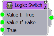
The Switches are typically the final node in a logic chain. There are two types. The Logic: Switch node can return a different numeric value depending on if the node wired to the Boolean input is true or false. You should use a switch node that matches the type of number you wish to return, there are options for Float, Integer and Scene Units.
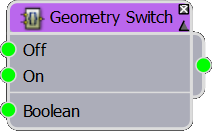
The Geometry switch chooses between two different segments depending on if the value wired to the Boolean input is True or False.
For both nodes, the Boolean input is usually attached to either a Logic > Conditional node, a Gate, or a Numeric or Constant parameter with its mode set to Boolean.
Transforms > Phyllotactic spirals
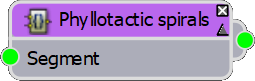
An unusual Macro created especially for a tutorial that creates Phyllotactic spirals, a fancy word that simply describes several kinds of patterns you find in nature (best exemplified by the seeds on a sunflower). To use it, wire it to the Default input of an L1S Generator. Wire a segment to its input. Now as you increase the Size property of the Generator, a spiral will be created. You can see the macro in action in the following tutorial.
Transform > Running Bond (Clipping)
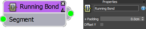
This node was designed to speed up the process of creating running bond paving patterns. To use it, we're a Brick or Tile texture to its input and wire the Macro to the Default input of an A2S generator. There are just two parameters: Padding, which adds a gap around the bricks, and Offset Y, which toggles the running bond pattern between a horizontal or vertical orientation. The GIF below illustrates both parameters.
This node was designed for ground and flooring applications - for brick walls, please try the Generator > Bricks and Walls macros
Related Post
Explore more articles from the ITOOSOFT team


You asked, we listened - Forest Pack 7 is out now with a glittering lineup of features and updates that cement its reputation as the most powerful and flexible scattering tool on the market.

Compatibility status of our plugins with 3ds Max with 3ds Max 2022