Требования
- info RailClone Lite, RailClone Pro
In the previous tutorial, we learned how to use and adapt the library. Now it's time to start creating our own styles. To do this it's important to have a good understanding of how base objects, segments and generators interact. In this instalment, we'll learn how to use an L1S generator to create a facade for the central building. Along the way, we’ll systematically go through the key settings that determine how a parametric object is constructed.
NB All the principals in this tutorial are also compatible with the free Lite version of RailClone.
Source Geometry
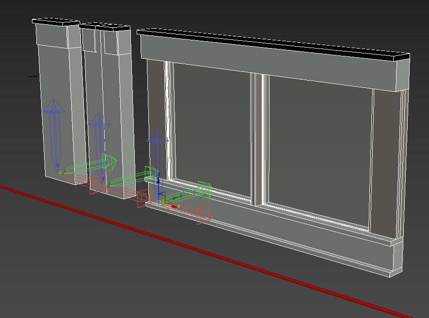
Before we open RailClone, let’s take a quick look at the source geometry we’re going to use.
When creating the meshes for a RailClone style. it's important to think in terms of how they will fit together like pieces of a jigsaw. In an L1S array, the axes of the source geometry are oriented so that the X-Axis follows the path of the spline, the Y-Axis runs perpendicular to the spline, and the Z-Axis is vertical, matching the RailClone object's local orientation.
In order for geometry to be correctly aligned in the array, it may occasionally be necessary to adjust the orientation of the local axis. To do this:
- Select the Geometry object.
- Go to 3DS Max's Hierarchy Panel.
- Click Affect Pivot Only.
- Rotate the gizmo to the correct orientation.
- Alternatively, you can just rotate the geometry to align to the world’s coordinate system and then reset the XForm.
As well as orientation, another consideration is the position of pivot points. In this example, we adjusted the pivot points of all the source geometry so that they are aligned on the Y and Z axes.
Finally a word on materials. There are two ways to handle them. You can combine all the materials assigned to the source geometry into one big multi-sub object material suitable for all the components. This material is then also assigned directly to the RailClone object. This has the advantage of being previewable in the viewports, but it also means that you have to manage materials IDs, and a complex material manually. Alternatively, when you create a new RailClone object, you can simply activate the Use Segment Material option from the Style rollout which will automatically use the materials found on the source objects. In this mode, there’s no need to create a global multi-sub material or remap IDs, but the material won’t preview in the viewports.
Creating the array
Now that we have our source geometry ready, we can create a new RailClone object.
- Go to the Create panel and add a new RailClone object to the scene then open Style Editor.
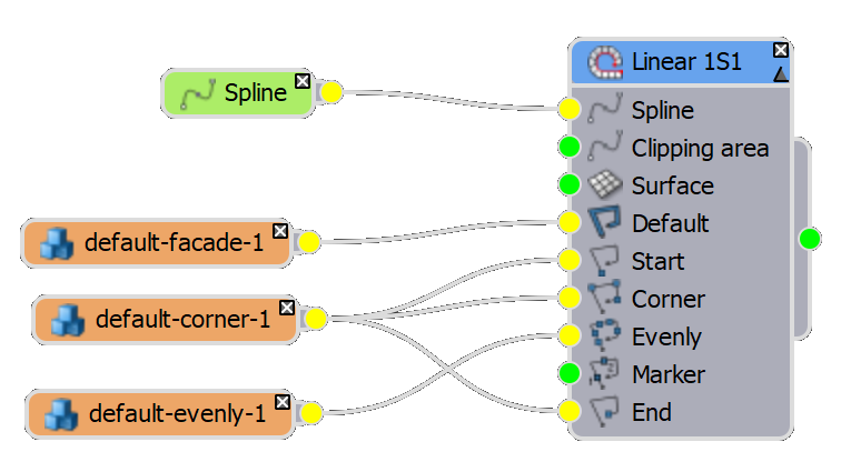
- The first thing we’ll need is a Generator, this is the brain of RailClone, it's where we’ll define all the rules that build the style. In this case, I'm going to use a linear, also known as an L1S generator.
- Next, I need to define a path. Create a new Spline node and wire it to the Generator's Spline input. Pick a spline from the scene.
![A Z shaped spline]()
When building a new style we like to temporarily use a simplified 3 section path with an internal and an external corner. Note that you can also assign the path from the Base Objects rollout in the Modify panel. - Now we can start importing the geometry. Add a Segment node and pick the Start/End geometry from the scene.
- Wire the Segment to the Generator's Start and End input. Pick the material from the source geometry and assign it to the RailClone object.
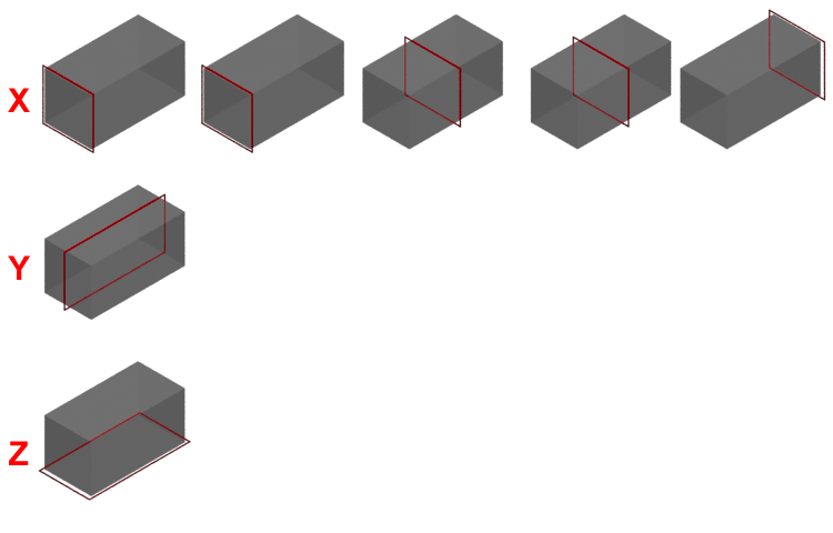
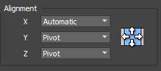
- Before we move on, let’s take a look at the Segment > Alignment settings. By default, the geometry’s bounding box is used to place segments. The bottom of its bounding box is aligned with the spline on the Z-axis, and the centre of the bounding box aligns with the spline on the Y-axis. On the X-Axis, however, the alignment depends on which input the segment is attached to.
![Alignment settings]()
- Generally speaking, unless you've got a very good reason to do so, I would leave X Alignment on Automatic, and the ones I regularity change are Y and Z. In this case, because the pieces may be different sizes on the Y-axis, I would change the Y Alignment to Pivot to ensure everything snaps together correctly.
![Alignment Settings]()
- All of the others segments should also use this same alignment, so to save from having to change that setting every time, I'm just going to clone the existing segment using CTRL+C then CTRL+V to copy and paste a new Segment node
- Now let’s pick the Default geometry and wire it to the Default input. The segment fills the spline between the existing Start and End segments.

Understanding the Rules tab
An important principle that’ll really help you to get the most from RailClone is to understand where the settings are for each of these inputs. When you want to control how geometry for a particular input is assembled, you will go to the Generator and open the Rules tab. Here you will find settings for Default, Corner, Evenly and Marker inputs. So let’s start with a look at the Default options
The Default Rules
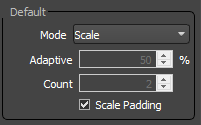
The segment used in the default input fills in between the Start, End, Corner, and Evenly segments. RailClone has 4 modes to determine how these segments are distributed along the path.
- First up is Tile mode. When this is active the default segments are replicated along the path, slicing the geometry at the end if necessary.
- Scale mode stretches a single segment along the path to fit the distance between the initial and final positions of the path section.
- Adaptive mode is one of the most useful, it calculates the number of whole segments that would fit along a spline section then scales them all equally to fill the available space. This mode always generates complete segments, with no slicing at the start or end of a spline section. In this mode the Adaptive value controls how much available space should be at the end of a path before another segment is added. It’s measured as a percentage of the segment’s size on the X axis.
- And finally there’s Count mode which allows you to specify a precise number of segments that will be scaled between the start and end positions of a path section.
The Corner Rules
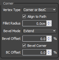
Now let’s take a look at the Corner input and its settings. Confusingly the Corner settings can actually affect the Default segments too, so we’ll take a look at a few parameters before we wire up any new geometry, starting with the Vertex Type dropdown which allows you to select which vertices generate a corner, and which do not. We’ll come back to Align to Path, but below this we have Fillet Radius. This option allows you to automatically curve any vertices identified as a corner.
Next we have the Bevel Mode option. This one can cause confusion because it only applies to the way that the Default geometry is sliced, it doesn’t affect the geometry that we’ll wire to the Corner input. You can use one of 4 modes
- None disables bevelling the default segments. Instead, it will try to bend the geometry around the corner, or if a Corner segment is present, it’ll stop the default geometry either side.
- Reset starts the geometry again, so you’ll get a full-width segment after the corner.
- Extends slices the geometry so that the length of the segment is maintained as if continues around the corner, giving an appearance of continuity.
- Finally, Symmetric matches the size of the segment on both sides of the corner.
Now let’s wire in a Corner segment. We’ll reuse the Start/End Geometry by wiring it to the Corner input.
- Let’s temporarily disconnect the Default segment so we can see better what’s happening.
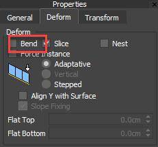
- The Corner geometry is placed on each vertex, and RailClone is currently attempting to bend it around the corner. In most cases, you don’t want to deform geometry in this way so to stop it bending, select the Corner Segment and go to its Deform tab. Disable Bend.
![Bend]()
- Now you can see that RailClone is rotating the geometry to bisect the angle of the corner. Alternatively, you can align the geometry to the previous spline section by disabling the Align to Path option. This is mainly useful for corners that are the same size on the X and Y-Axis. For example, this mode works particularly well for things like fence posts. In that scenario, I’d turn off Align to Path and change Bevel Mode to None to stop the default geometry from continuing through the post.
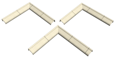
- For our facade, we want to bevel the corner segment. To do that, you check the Bevel Corner option. When this is enabled, the segment is repeated on both sides of the corner, and is sliced to maintain its full length on the outside of the corner. You can adjust this slice position using the BC Offset option.
- Plug the Default geometry back in and you’ll notice that with Bevel Corner enabled, the default segments no longer continue to the corner, although the Bevel mode is still taken into consideration. In most cases though, you’ll probably use Adaptive or Scale mode, which removes corner slicing for the Default segment completely, since only whole pieces are used.
The Evenly Rules
Now that we have segments at the Start, End, on Corners, and filling in between, let's finish the tour of the Linear generator by adding geometry that’s spaced at regular intervals along the path.
- Clone one of the existing segments, and pick the Evenly geometry from the scene.
- Wire it to the Evenly input. The geometry is added to the spline, but the spacing is far too close together. Go to the Rules tab and find the Evenly settings.
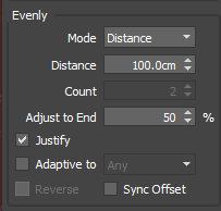
- First of all, Distance allows you to control the spacing between the evenly segments. The Adjust to End parameter is measured as a percentage of the distance’s size and it determines the threshold at which a new Evenly segment is added.
- The Justify option, which is enabled by default, adjust the first and last space to make the evenly segments fit within the spline. The remaining spacing is always exactly the distance value
- An alternative mode is called Adaptive. In this mode, all of the spaces are subtly resized to fit the evenly spacing along the path. All sizes should be the same (although this doesn’t take into consideration the size of the Start, End or Corners).
- In Adaptive mode, you have 3 further options. You can either force an Even number of divisions, an odd number of divisions, or you can use any number of divisions, odd or even as the length determines to be most appropriate.
- Finally, you can also turn off Justify and Adaptive completely, in which case the evenly segments are measured precisely starting from the beginning of the spline section. Only the final section will be a different size. In this mode you can also change the direction these are calculated using the Reverse option.
Other Settings
That completes this basic style. Of course, this would be much quicker to create in a real production setting, but we’ve taken the time to go over nearly all of the key rules that determine how a linear array is constructed. Before we finish this tutorial, let’s just take a quick look at a couple of the other useful generator settings.
Limits
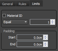
- First of all, switch to the Limits tab and you’ll find two Padding settings. These allow you to offset the Start and End of the array, basically shortening it by a set distance.
- There’s also an option here to limit the generator by a material ID assigned to the Spline. To illustrate, change the material IDs on the spline sections. Now enable the Limit by Material ID option, you can then choose to limit to just one of those IDs, or even use a comma-separated list to target several.
General
If we switch to the General tab, we can find even more handy settings.
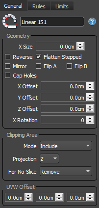
- Starting at the top, we have a Reverse option that reverses the path, but without you having to change the base spline manually.
- Cap Holes will fill in any parts of the array that gets sliced.
- X Offset, translates the array on the X axis.
- Y Offset expands the path to one side of the spline. This setting is particularly interesting when used in conjunction with the Mirror checkbox above. When this is active, you are actually creating two versions of the array, one on each side of the spline. You then have options to Flip either or both of the arrays as required.
- Moving down, Z Offset does what you’d imagine, it translates the whole array on the Z-axis
- Finally, X Rotation rotates the array using the path as a pivot.
Phew - lots to take in. I think we’ll call that a day for this tutorial, we’ve covered some of the most important settings found in the L1S generator and explored how you can create a basic style, but also hopefully more crucially, as you work with RailClone you’ll really understand why you’re using those settings.
In the next part of this series, we’ll finish this model and explore how Operator nodes can be used to randomise, select, sequence and group geometry for even more sophisticated styles. See you there!