Требования
- info RailClone 2.4
RailClone 2.4 New Features Tour
Introduction
RailClone 2.4 introduces a host of new features focused on improving usability. In this tutorial we'll take a tour of some of the most significant, and explain how to use them so you can start working faster right away.
This features tour contains the following sections:
New Features
UVW XForm Operator
The UVW XForm operator allows you to easily edit and randomise the offset, tiling and rotation of existing UVW coordinates. It's particularly useful in those scenarios where you need a lot of texture variation, but you don't want to have to create time-consuming multi-sub object materials and randomise material IDs. (Of course for even more variation - both techniques can be used together!)
Compatibility
V-Ray is required to maintain instancing when using this operator. Other renderers are supported by disabling instancing. To do this, turn off Display->Use Instancing Engine. To see a full list of which features are supported by your renderer, check the compatibility list.
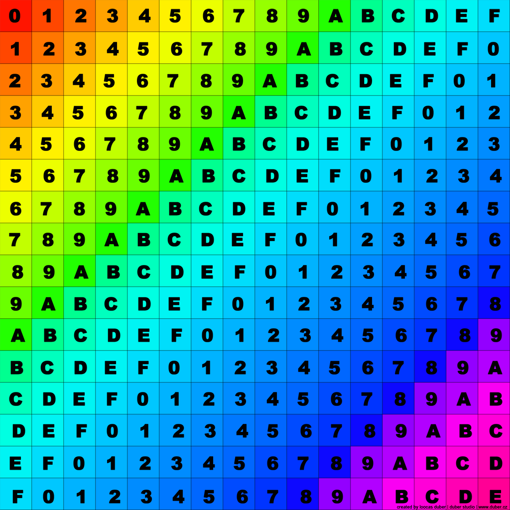
To help illustrate how the operator works, in the following examples the texture shown above has been applied to a simple tile mesh. The object has been mapped before adding it to the RailClone style so that only one of the 256 coloured alphanumeric tiles is displayed.
To adjust UVWs
To use the new operator to adjust UVWs for all segments identically, simply follow these steps:
- Wire segment(s) to the UVW XForm operator’s input.
- Use the UVW XForm operator's properties to change the Map Channel, or if you'd prefer to affect all the channels, turn on Apply to All Channels. If you want to adjust a limited selection of channels, for example map channels 1 and 3, you can use multiple UVW XForm operators wired together in series.
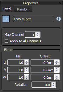
- The Fixed group allows you to edit the Tiling, Offset, and Rotation of the existing mapping. There are independent controls for each of the U,V and W axes.
![RC 2.4 Feature Tour-image2015-3-5 18:3:19.png]()
To randomise UVWs within a range
The UVW XForm operator also includes powerful randomising features. Using these you can create a tremendous amount of variation from a single map. To do this:
- Still in the UVW XForm operator's properties, switch to the Random tab.
- You can now randomise offset, rotation, and tiling between a set range defined by adding a Start and End value.
For an example of this technique in action, let's take a look at a cladding style. It uses this texture:
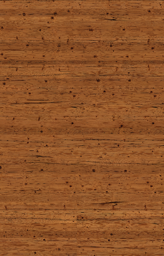
As in the previous example, the plank segment has been mapped prior to importing into RailClone so that only a small portion (a single plank) is displayed:
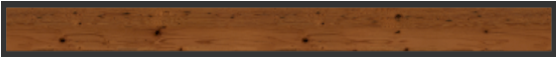
Single Board
Here's how this looks on a facade, as you can see the texture repetition is obvious.
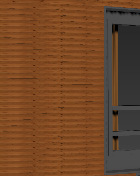
Facade with Standard UVs
Now if we go back to the UVW XForm Operator and turn on Random > Offset and enter a Start and End value to define a range of 0 -1 for the U and V axes, we get a lot of variation with very little obvious repetition.
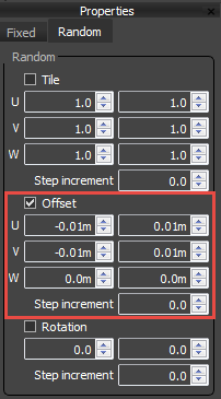
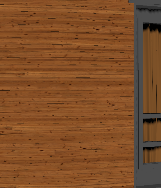
Facade with randomised UVs
Why 0.01m?
The spinners in the UVW XForm operator use scene units. If you're using real world map sizes this makes sense and behaves as you'd expect, but if you're using standard mapping, it's not necessarily obvious what measurements correspond to 0 - 1 in UVW space. The answer is that 0 - 1 UVW space corresponds to 0 -1 system units. To find out what your system units are go to Customise > Units Setup and click on System Unit Setup.
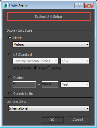
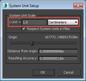
In the facade example above, the scene's system units are in centimeters, and the display units are in metres, which explains why 0.01m is used for the offset value.
To randomise UVWs using stepped increments
As well as selecting any value from within a set range, you can also constrain the UVW XForm operator to use only increments of given step value. For example, you could set the rotation range from 0 to 360 degrees, then by using a step increment of 90, you ensure it only returns values of 0,90,180, and 270. You can do the same thing for Offset, and tile.
Let's take a look at a typical usage. In this example I have a single tile object and one texture with 25 tiles in a 5 x 5 grid. Using the old workflow we'd have had to slice this texture up and create a multi sub object material with 25 material IDs. Using this operator we now only need 1 material.
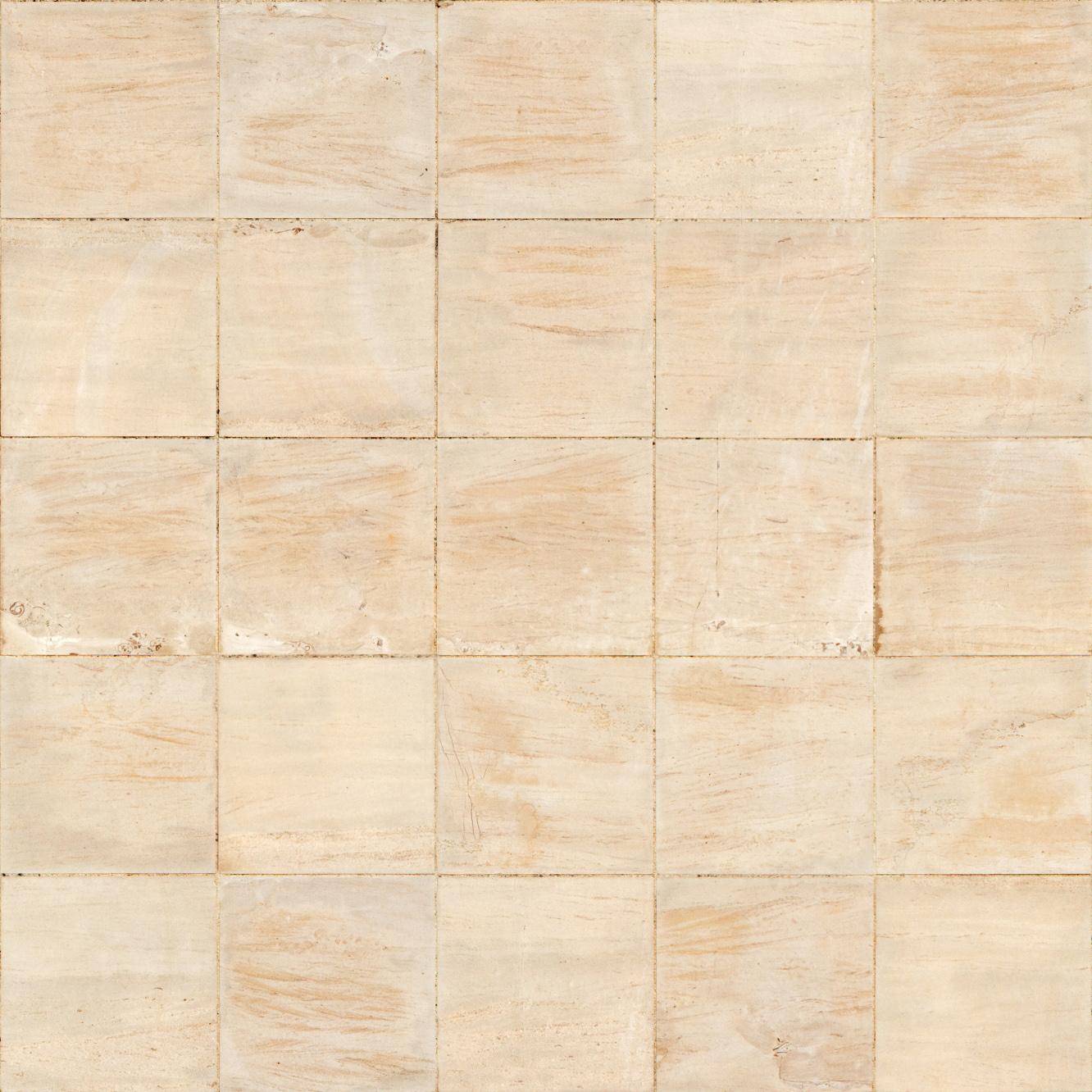
As in the previous examples. You ould already have edited the UVs on the segment's source geometry so that only one tile is displayed. Then, to randomise between all 25 tiles:
- Wire the tile segment to a new UVW XForm operator.
- Go to the Random tab and activate Offset
- Add a Start value of -10mm and an End value of 10mm to define the U and V ranges (assuming the scene units are set to centimeters, and the display units are in millimeters).
- Enter a Step Increment value, this should be the UV space divide by the number of tiles along a side. In this case that's a UV space of 1 divided by 5 tiles, so we need to enter 0.2. The random values returned by the operator will be multiples of this figure.
- We can add further variation by randomising the Rotation. Enter a Start value of 0 and and End value of 360.
- Next enter a Step Increment value of 90 degrees.
After applying this operator the textures displayed on each segment will now be one of 25 tiles, with 4 possible rotation angles.
Exportable Attributes
It's often desirable to use the size of a segment's geometry to drive other properties or expressions in a a style. Previously we had to hardwire these values into the style using a Numeric or a Constant parameter. In RailClone 2.4, it is now possible to export the current size of a segment from any node. To do this:
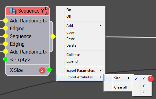
- Right click on a node, select Export Attribute and choose the attribute to be exported.
- The exposed attributes will be added to the bottom of the list of output slots.
Let's take a look at an example. In this style the height, width and depth of the table is being used to automatically place the plates, cutlery and bottles. In addition to being on top of the table, the plates are always halfway along the tables length and width. Because these values are derived from the segment's dimensions, we can easily change the table, and the objects on top are re-positioned automatically. More or less any object could be added to this setup and these items will adjust to match, even a table with adjustable height, length and width (also parameterised with RailClone):
Evenly Count Mode
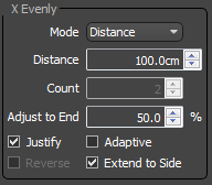
RailClone 2.4 introduces a new Evenly mode. The original mode is now renamed Distance, and behaves exactly as before. In this mode evenly segments are distributed according to a distance parameter: as the size of array increases, additional evenly divisions are created.
In the new Count mode, which can be selected from the dropdown list found in the Rules > Evenly group, the array is divided using a fixed Count value. Irrespective of the size of the array, the number of evenly divisions remains the same. In this example you can see that the number of houses in this terrace is unchanged, even as the array is lengthened.
Generator Padding
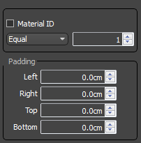
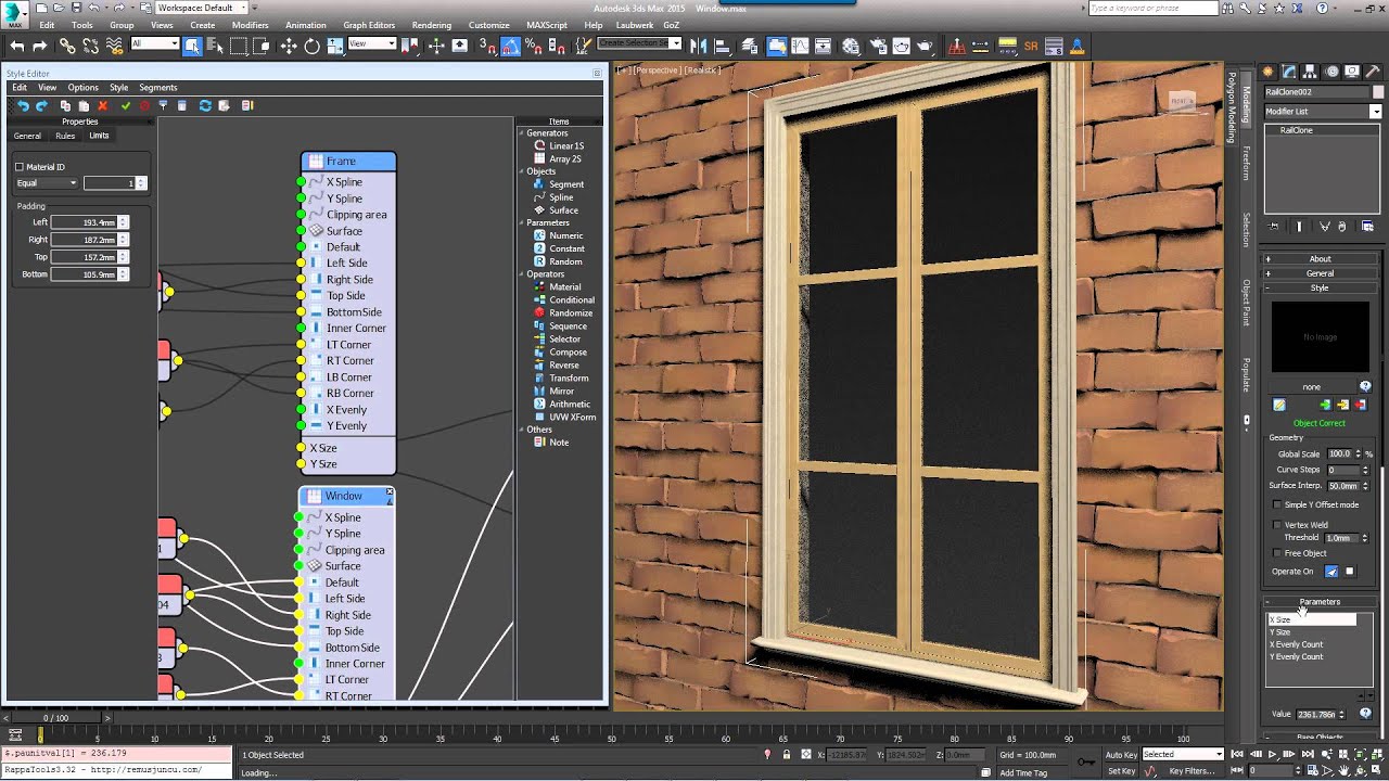
Generators can now use padding values. These are used to add offsets to the left, right, top and bottom of A2S generators, or the start and end of L1S generators. All calculations, such as evenly spacing, are based on the new lengths of the array after the offset has been applied. This is particularly useful for instances where you need multiple generators to jigsaw together. For example, this window style has one generator to create the surround, it uses the full lengths of the array on the X and Y Axis:
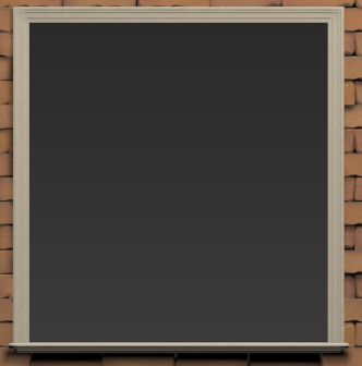
A second generator creates the windows itself. To prevent it from overlapping the outer surround, padding is added to the top, bottom, left and right of the generator. This style also uses Evenly Count mode to ensure that the amount of vertical and horizontal elements remains the same as the window is resized.
Box mapping multiple channels
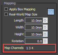
RailClone has always been able to Generate box-mapped UV coordinates that conform to follow the array. When this feature is turned on, Instead of using the default UV coordinates of the the individual segment, continuous mapping is seamlessly tiled along the length of the RailClone object. Until now it has only been possible to UV map one channel. RailClone 2.4 introduces the ability to box map multiple channels. All that's needed is to add the channel numbers in the Map Channels input separated by a space.
Style Descriptions
If you're making styles to be used by other people in your studio, or even for wider distribution, it's helpful to be able to include a description and instructions-for-use that can be easily accessed directly within 3DS Max. Version 2.4 includes the ability to add text descriptions, to do this:
- Open the Style Editor.
- From the Style dropdown menu click
![RC 2.4 Feature Tour-image2015-3-3 10:7:20.png]() to open the Style Description window.
to open the Style Description window. - Enter a description, normally this will contain information for new users about how to use the style. You can also see a list of all the base object and parameters used.
![RC 2.4 Feature Tour-image2015-3-3 10:11:27.png]()
- Click OK.
 to open the Style Description window.
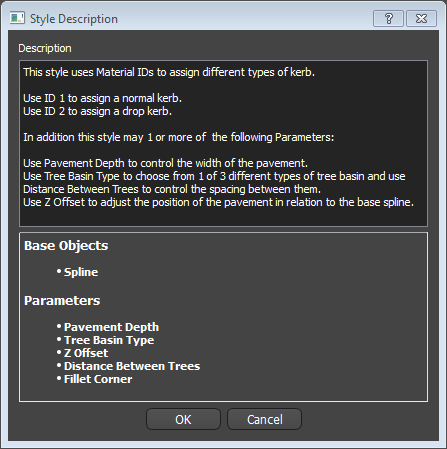
Then to view the description without opening the style editor:
- Go to the modify panel, open the Style rollout and click
![RC 2.4 Feature Tour-image2015-3-3 10:14:1.png]()
- A dialog opens containing the style's description, including the base objects and parameters used.
![RC 2.4 Feature Tour-image2015-3-3 10:19:56.png]()


Style Editor Improvements
In addition to the features we've already mentioned, there's a host of style editor workflow improvements to help speed up the creation process.
Import multiple segments
Importing multiple segments was always high up on our wish list. For example, imagine you are creating a a style with a sequence comprising 20 segments. Importing them the old fashioned way, one at a time, used to take a while. In RailClone 2.4 the process is much simpler:
- Create a new Segment Object (
![RC 2.4 Feature Tour-rc_a2s_add_segment.png]() )by dragging from the Items List to the Construction View and enter any general, deform, or transform settings you want to be used for all segments before going any further. This node will be used as the template for the other segments so it's important to add these settings now to avoid doing it 20 times afterwards.
)by dragging from the Items List to the Construction View and enter any general, deform, or transform settings you want to be used for all segments before going any further. This node will be used as the template for the other segments so it's important to add these settings now to avoid doing it 20 times afterwards. - Right Click on the new Segment and select Clone Multiple.
![RC 2.4 Feature Tour-image2015-3-4 11:44:21.png]()
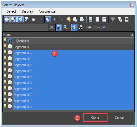
- A Select Objects window opens. Pick the objects in the scene you wish to add to the RailClone style and click Clone, RailClone will generate a new Segment node for each of the selected items
![RC 2.4 Feature Tour-image2015-3-4 11:51:3.png]()
 )by dragging from the Items List to the Construction View and enter any general, deform, or transform settings you want to be used for all segments before going any further. This node will be used as the template for the other segments so it's important to add these settings now to avoid doing it 20 times afterwards.
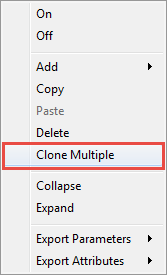
You will now have all 20 segments imported, each using the same settings as the cloned source.
Multiple Wiring Support
Of course bulk importing segments isn't much help if you still have to wire them one at a time. Thankfully RailClone 2.4 can save you time here too. It's now possible to wire multiple nodes to Compose, Sequence, Random, and Selector operators. To do this:
- Marquee select the nodes you wish to attach.
- Drag any of the nodes outputs to the operator's input.
These two improvements used together should save a lot of time for styles that use a large number of segments.
To swap the connections for two nodes
Another time consuming situation is when you want to swap a node that is connected to a lot of inputs. Previously you'd have to have reconnected each one manually. Now all you need to dp is to drag the output of one node onto the output of another, and all of their connections will be automatically swapped.
Auto Renaming nodes
To save you valuable typing time, nodes connected to exported parameters are now automatically renamed.
To clear all exported Parameters or Attributes
If you've exported a number of parameters or attributes you no longer need, you can now clear them quickly by right clicking on the node, going to the Parameters or Attributes menu and click Clear All
Exportable Randomise > Presence and Sequence > Counter parameters
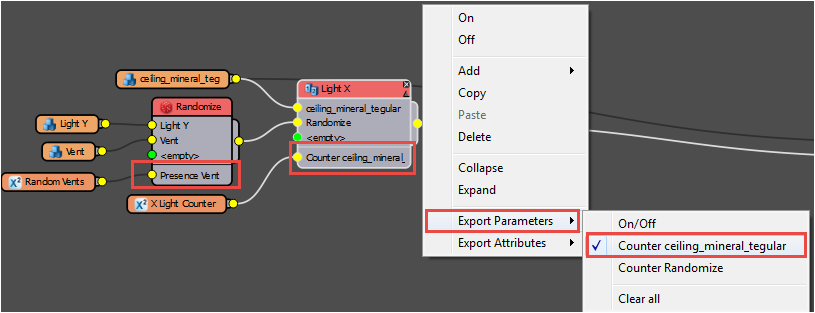
In addition to making parameters easier to find, add and remove, we've added some brand new ones. Dynamically generated parameters like the Count value on the Sequence operator and the Presence value for the Random operator can now be exported and wired for editing from the modify panel.
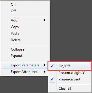
All nodes have an on/off exportable parameter
We have also added an On/Off exportable parameter for all nodes to enable you to easily enable/disable features of your style. To use it :
- Right click on a node, click Export Parameters and Click On/Off.
![RC 2.4 Feature Tour-image2015-3-8 11:43:32.png]()
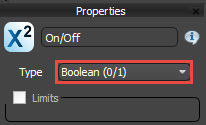
- Create a new Numeric node and wire it to the Exported On/Off input. Set the type to Boolean and rename it if necessary.
![RC 2.4 Feature Tour-image2015-3-8 11:44:22.png]()
- You can now enable and disable the node from the Parameters rollout in the modify panel. For operators that use multiple segments, the one attached to the first input is used if the node is disabled.
Libraries
Finally, RailClone 2.4 introduces the first phase of our library overhaul. In this release you'll find improved styles in the Architecture->Exterior->Fences->Metal and Vinyl libraries, the Architecture->Interior->Railings library. In the Civil Engineering category, the Pavements > Curbs and Sidewalks libraries have been revamped.
Many of these new styles make use of the base Spline's material IDs. For example the Vinyl Fences use Material ID 2 to add a gate, while the Pavements use ID 2 to introduce a Drop Kerb. To see how to use a style you can always click on the Help button in the Style rollout to bring up a description and usage instructions.
Conclusion
We hope you enjoy these new features and improvements and find them useful in your work. This is only a selection of the most significant changes and fixes, for a full list we recommend checking out the full Release Notes on our website. Stay tuned for more tips and tricks videos, or to find out more about RailClone please see our website, the updated reference section or visit the tutorials page.