Resources
Requirements
- info RailClone Pro
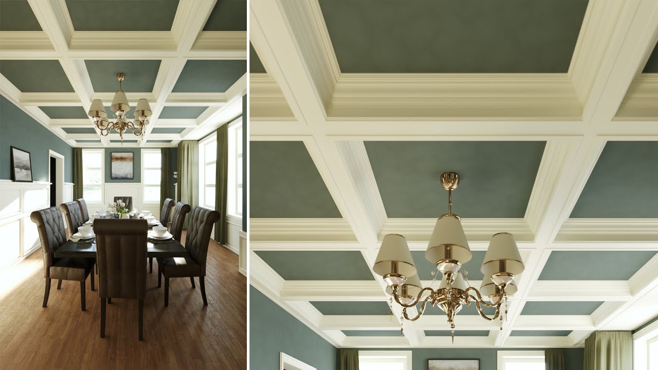
In this tutorial we’re going to demonstrate how to make a parametric coffered ceiling that allows you to define the size and position using a rectangular spline, as well as adjusting the spacing between the horizontal and vertical beams.
Really though, this is an excuse to demonstrate the main inputs of the A2S Generator PLUS a handy macro called Segment Y Role that allows you to target bits of a 2D array that aren’t normally accessible without resorting to an expression. These parts include the intersection where the horizontal and vertical beams cross, as well as the T-Shaped intersection where they meet the sides. This tutorial is therefore useful for a very wide variety of objects, and the techniques demonstrated could also be seen as a successor to our older windows tutorial.
In most of our tutorials, we start with the source geometry already modelled, but a few users have asked for a little more information about preparing the assets for RailClone, so in this tutorial, we’ll start from nothing and demonstrate the modelling process from start to end. If you’d like to follow along, then scene files are available from the iToo Software website.
Modelling
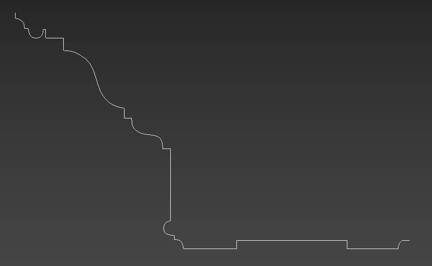
First of all, we need to model a section of ceiling that can be sliced into a jigsaw of pieces to become a parametric object. There are lots of ways to do this, but in this example, I’ll trace an image of a typical profile using a spline, and then covert it to polygonal geometry using the Bevel Profile modifier. To do this
- Find yourself a picture of a profile (or make one up!).
- Add the image to a plane so it can be traced.
- Create a new Line object and trace the profile. I only trace one side of the profile so that we can create the perimeter of the ceiling. We’ll create the double-sided profile used by the interstitial beams using a Symmetry Modifier in the following steps.
![]()
- If necessary, scale the spline to the correct size and then reset the XForm.
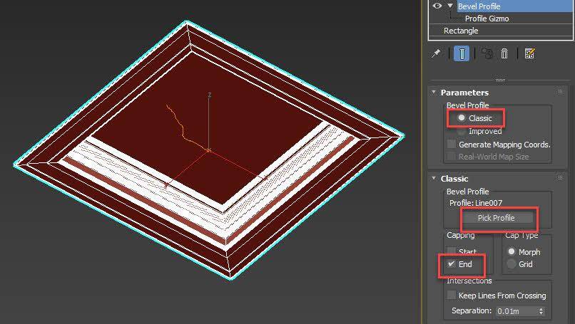
- To turn this into the panelling. Create a square rectangular spline about 1m on each side.
- Add a Bevel Profile modifier, and change the mode to Classic. This mode allows us to use a spline to define the profile instead of the modifier’s built-in graph.
- Click on Pick Profile and select the ceiling profile spline from the scene.
![]()
- If necessary, add a Normal modifier to the object and enable Flip Normals. This is a ceiling so we want the face direction to be downwards.
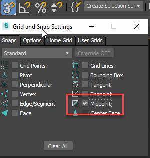
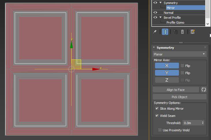
- Now we have a single panel, but we want a model that includes a central bar, plus a junction where they meet the sides and in the middle. To do this we use one or more symmetry modifiers. In 3ds Max 2022 and above you can use just one modifier since it has been improved to do multi-axis slicing. In the earlier versions you’ll need to use two modifiers, but the principle is exactly the same.
- Enable X and Y symmetry.
- Turn on Snaps and Right-click to open the Snaps menu. Enable Midpoint.
![]()
- Go to the Symmetry Modifier’s Mirror sub-object level.
- Move the gizmo so that it snaps to the midpoint of the bottom left diagonal edge. This should give you a nice proportionally sized perimeter as well as a cross member on the X and Y axes. If you move to any corner other than the bottom left, you’ll need to use the modifier’s flip settings to create the same effect.
![]()
- If you plan to use multiple materials, then add an edit poly modifier and assign material IDs. Here I used material ID 1 for the ceiling and an ID of 2 for the beams.
Slicing
We now have the basic geometry. To create a flexible RailClone style we can slice this into several parts. In fact, I will create 16 pieces divided into 4 rows, starting from the bottom upwards they are as follows:
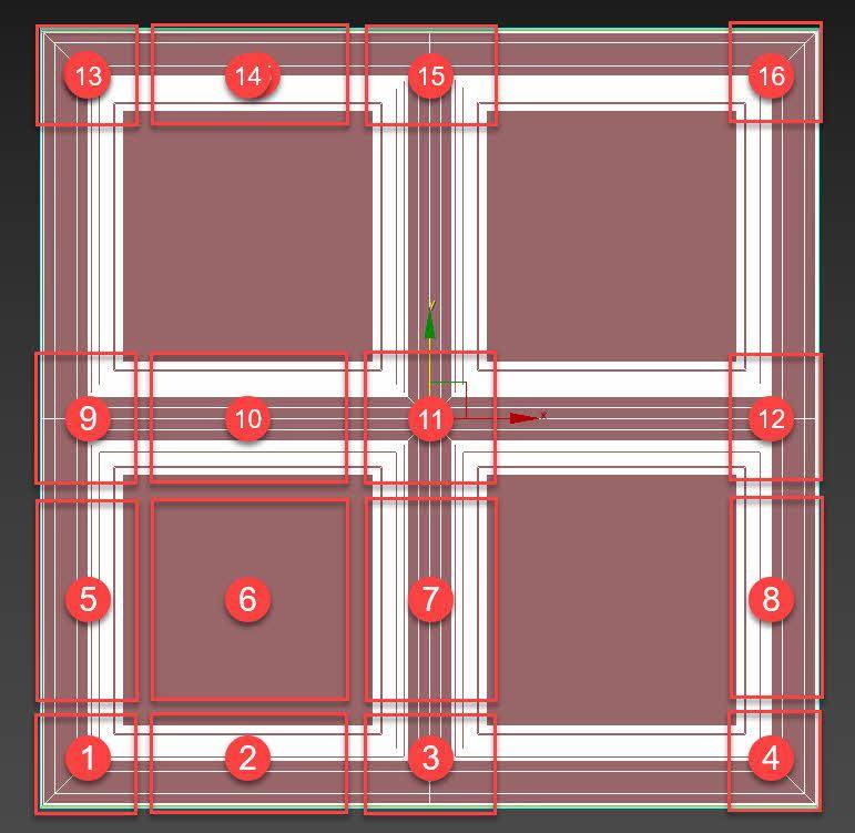
- Start - Bottom
- Bottom
- X Evenly - Bottom intersection
- End - Bottom
- Start
- Default
- X Evenly
- End
- Start - Y Evenly intersection
- Y Evenly
- X Evenly - Y Evenly intersection
- End - Y Evenly intersection
- Start - Top
- Top
- X Evenly - Top intersection
- End - Top
To create these from our geometry the easiest way is with Slice modifiers. This can be done manually, but because this process can be a bit tedious we have an unofficial script we use internally called RailClone slicer. It’s available in the downloads for this tutorial.
The script allows you to create and control all the necessary Slice modifiers from a single interface to prepare models for both 1D and 2D arrays. Just drag it to the Max viewport to run and then it’s pretty straightforward to use:
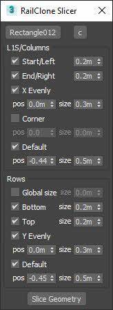
- First of all, click the Pick Geometry button and select your geometry from the scene
- Next we enable the elements we wish to create slices for. So we’ll begin with the Start. Enable the checkbox and increase the distance to move the slice plant until it is just past the left beam. Note the value, it might be easier to use it again for the other entries.
- Now do the same for the Right side. I’ll copy and paste the value.
- Several of the slices have two values: Position and Size. For X-Evenly we’ll leave the Position centred but increase the Size so that the slice planes are on either side of the central beam.
- On the other hand, for the Default segment you’ll need to move the position to the centre of one of the panels.
- That takes care of the slices on the X-axis, now we’ll slice on the Y-axis.
- Disable Global Size since we’ll need to use a couple of different slice sizes.
- Enable Bottom and increase the size. Do the same for Top.
- Enable Y-Evenly and increase the size to encompass the middle beam.
- And finally, enable Default and move the position to the centre of one of the panels. Increase the size.
- Once you’re done, click on the Slice Geometry button and the script will create all 16 parts automatically. To remove the slice planes from the original geometry when you are done you can click on the C button.
![]()
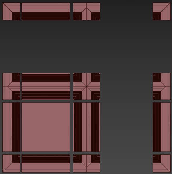
Now all we need to do is to pop these parts into a new RailClone style.
Creating the RailClone style
- First of all, create a rectangular spline to define a temporary ceiling area. Then, create a new RailClone object and go to the Modify panel.
- Open the Style Editor and add a new A2S generator. This generator is used any time you wish to create 2-dimensional arrays. As we will see, it constructs the objects in a grid by allowing you to target specific parts of the array with different geometry. Before we add geometry though, we need to specify the size of the array, and we’ll do that using the closed spline we just created.
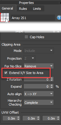
- Go to the Generator’s settings and enable Extend X/Y size to Area. When this is enabled, RailClone will automatically calculate the size of the array to fill a closed spline wired to the Clipping Spline input.
![]()
- Let’s add that spline. Create a new Spline node and pick the spline from the scene. Wire it to the Clipping Area input.
- Now we’ll add the geometry, starting from the bottom. Add a new Segment node and pick the Start - Bottom segment from the scene. Wire it to the input with the same name.
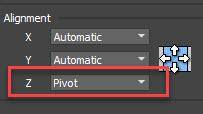
- There’s one setting we’ll need to change for all the segments, and that is how they align on the Z-Axis. By default, RailClone will align segments on the Z-axis using the bottom of their bounding box. Because several of the segments we created earlier are different heights, this would result in them not aligning correctly. To fix it, we go to the Segment’s Alignment settings and change Z to Pivot.
![]()
- To save doing this every time, we’ll copy and paste this segment to import all the other geometry.
- Clone a Segment node and select the End - Bottom geometry from the scene. Wire it to the input with the same name.
- To fill in between, clone the Segment node again, wire it to the Bottom input and pick the appropriate segment from the scene.
- Now we’ll do the same for the top. Clone and wire the Start -Top, End - Top and Top segments to their relevant inputs.
- To fill between the top and bottom, clone a Segment node again and select the Start geometry. Wire it to the Start input.
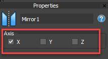
- Now, you may have realised by now that it may not actually be necessary to create so much geometry because much of it is identical only mirrored on the X and Y axes. So to demonstrate an alternate approach we’ll show how you can reuse the Start geometry for the End input. All you need to do is wire a Mirror operator to the End input and then wire the Start segment to that. By default, this node flips geometry on the X-axis. There are further options to flip on the Y and Z axis so you could actually get away with far fewer segments than I’m using here.
![]()
- We now have the perimeter done - to fill in the remaining area, clone a Segment node once more and select the Panel geometry from the scene. Wire it to the Default input. We now have a parametric panel done. If you change the size of the spline, the panel size also changes.
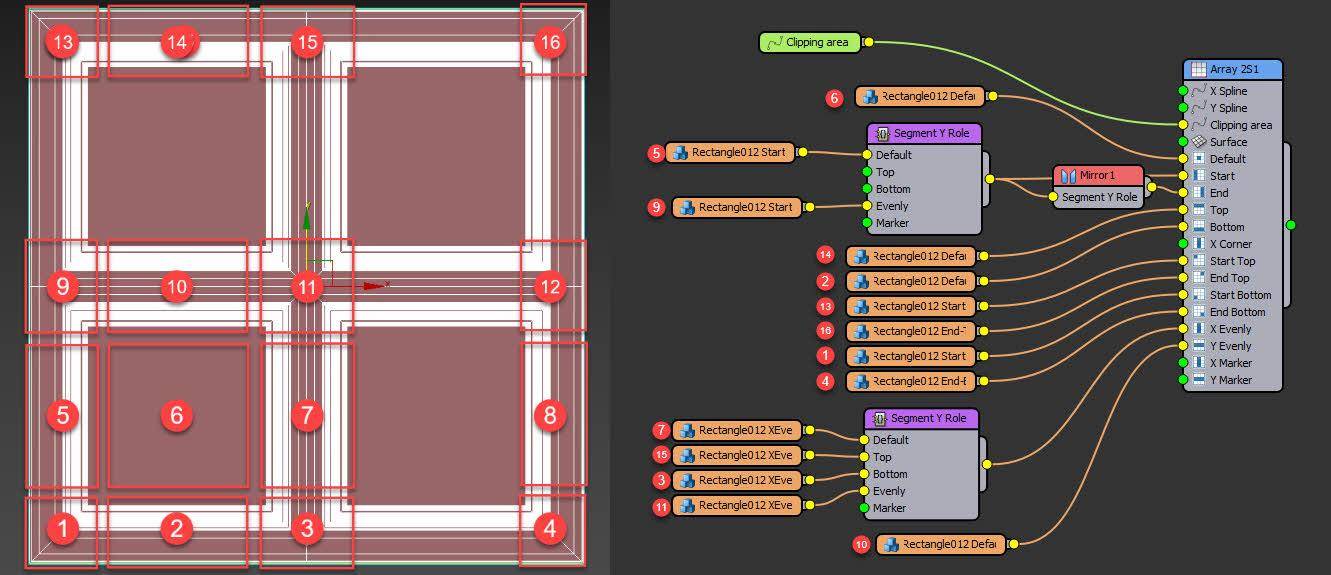
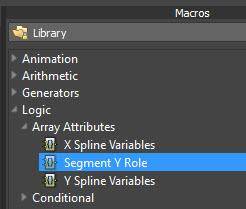
- Now lets add divisions on the X and the Y axes. If we refer to the original model, we need an input for where the vertical divisions meet the top and bottom, where the horizontal divisions meet the start and end, and where the divisions intersect. But as you’ll notice, there’s actually only one input each for the X Evenly and the Y Evenly divisions. This is where a new Y Role macro comes in. It an be used in any vertical input such as Start, End, X Evenly, X Corner, and X Marker and it adds several additional inputs as we’ll see
- Add a Segment Y Role Macro to the X Evenly input.
![]()
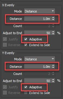
Clone a Segment node and pick the X Evenly geometry from the scene. Wire it to the Macro’s Default input. This is the same as if we’d wired it directly to the generator’s X-Evenly input. To change the spacing, go to the Generator’s rules and adjust the Evenly Distance settings. While you’re here, I’d also enable Adaptive mode for both evenly axes which will give you a more even distribution instead of scaling only at the beginning and end.![]()
- Now, as you can see, we’ve broken the array a bit. That’s because we don’t have segments yet for the top and bottom intersections. Let’s fix it! Clone a segment and pick the X Evenly - Bottom segment from the scene. Wire it to the Macro’s Bottom input.
- Do the same thing for the X Evenly - Top segment. This time wiring it to the Macro’s Top input.
- Now lets add the horizontal divisions. Remember I said that the Y Role macro is only used in vertical inputs. That means that we don’t use it in the Y Evenly input. Instead we’ll just add the Y Evenly Segment as normal.
- So where do we use the Y Role macro? The answer is in the Start and End inputs, as both of these these are targeting vertical parts of the array. We can add one after the existing segment, wiring the segment to the Macro’s Default input.
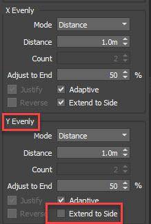
- There’s another thing we need to change. Select the Generator and go to the Rules tab and scroll down to the Evenly settings. You’ll notice that by default the X Evenly and Y Evenly Extend to Side options are Enabled. In order for the Macro to work, the Y Evenly Extend to Side option needs to be Disabled. This setting determines whether the segments wired to the Evenly inputs extend to the sides or not.
![]()
- Now we’re ready to add the remaining segments. Clone a Segment node and pick the Start - Y Evenly geometry from the Scene. Wire it to the Macro’s Evenly input. You’ll see the geometry appear on the sides!
- There’s one last piece of geometry we need to target, and that’s where the X Evenly and Y Evenly divisions intersect. To do that we go back to the Macro wired to the X Evenly input. Clone a segment and wire it to the Macro’s Evenly input. Pick the Intersection from the scene.
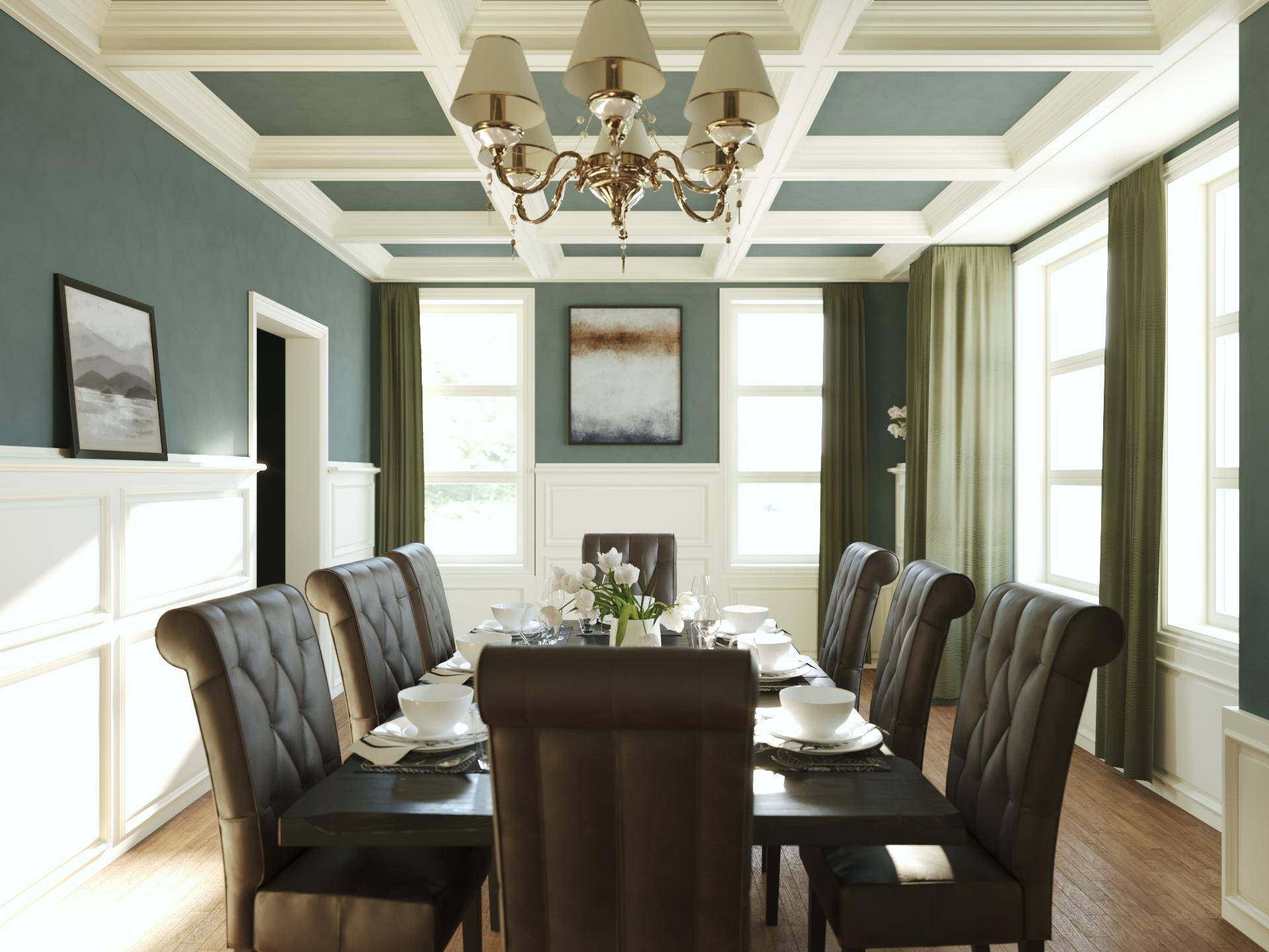
- Assign a material and the style is now complete! We can quickly assign it to any rectangular spline to create a procedural ceiling of any size!
Sometimes we get comments that maybe a simple ceiling like this could have been done quicker manually - and for one-off projects that might be true. But in every case what we aim to produce an asset that can be reused again and again saving time in the future, and one that can be easily adjusted should the architect request changes. So with that in mind, in this final step, I’ll add a couple of parameters for the X Evenly and Y Evenly spacing that can be controlled directly from the Modifier panel.
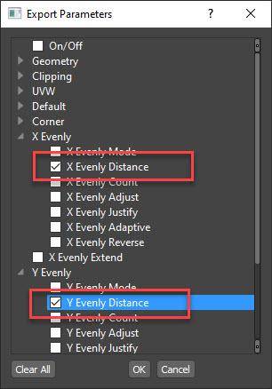
- Right-click on the generator and select Export Parameters.
![]()
- Check X Evenly and Y Evenly distance and click OK. New inputs will be created.
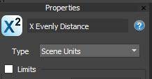
- Create two new Numeric nodes.
- Change their type to Scene Units.
![]()
- And finally, wire them to the new inputs.
- You can now control the spacing from the Modify Panel.
And that concludes the tutorial. Now, although this tutorial used the example of a coffered ceiling, the techniques and the understanding of how the A2S segments jigsaw together will help you to create a huge number of different types of objects. In fact, the windows and cladding were created in exactly the same way. 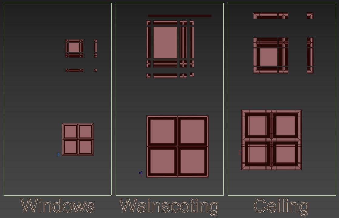
If you open the scene you can explore the graphs and see how the same type of base geometry was used. Once you’ve done this once or twice, you can even just swap the geometry in the segments to create different parametric objects in a matter of minutes!
We hope you enjoyed this tutorial, If you haven’t already, please feel free to subscribe to our YouTube channel to get notifications for more handy tips on how to use RailClone and Forest Pack coming soon.