Requirements
- info 3DS Max 2011, Forest Pack Pro 4.3, RailClone Lite/Pro 2.4
Introduction
Forest Pack isn't just for plants. It's also well suited to adding furniture and characters to the interiors of large buildings to quickly fill a huge area over a number of floors. Instead of painstakingly placing thousand of objects, let Forest Pack do the heavy lifting for you and scatter random types of furniture on each floor. In this tutorial we'll share a collection of tips and tricks for populating building interiors focusing of 3 possible scenarios:
- Adding furniture to buildings where each floor is a separate object.
- Adding furniture to buildings where the floors are combined and separating them would be too much work.
- Adding furniture to buildings where the floors are created with RailClone.
For each of these scenarios we want to be able to do the following.
- Randomise objects per floor.
- Avoid interpenetration with façade/internal walls as much as possible.
- Include the ability to add vertical zoning.
- Randomise textures etc - screens on computers, chair colours in this case. (Forest Colour).
- Use UV transform to align objects to the perimeter of the building.
As a bonus, we'll also look at how to create the floor plates using RailClone, and examine how Forest Pack and RailClone can work together to create a fully parametric system that includes façade, floors and furniture.
Download Contents
The exercise files for this tutorial includes the following .max scenes compatible with Max 2010 and V-Ray.
- fp_populate_buildings_start.max The starting file if you want to follow the tutorial.
- fp_populate_buildings_start.max The starting file if you want to follow the tutorial.
All furniture and computer models with the exception of the desk are used with the kind permission of Dimensiva. For many more high quality free models please check out their website. This tutorial also uses several Populate characters that have been collapsed to an editable mesh, but for better results you may wish to source 3rd party character models.
The Screens on the Macs, the chairs and the seated people have had their textures randomised for more variation using the Forest Colour map, you can find an depth tutorial on this here.
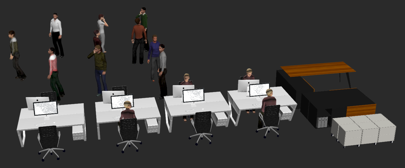
The objects scattered in this tutorial
Scenario 1 - Floor plates are separate objects
To use this mode you will need to add each individual floor to Forest as a separate surface. Adding surfaces separately retains most of Forest Pack's features and is very easy to use.
Preparing Geometry. To group or not to group
Creating the Furniture Forest object
- Open fp_populate_buildings.max.
- Create a new Forest Pack object by clicking on the surface called Individual Floor Plates. Name the new object fp_furniture.
- Go to the modify panel and open the Surfaces rollout. Using this rollout we can add and remove surfaces as well as controlling the modes, alignment, and limits based on altitude and slope angle. For now we just need to add the remaining floor plates, to do this, click on Add Multiple
![Populate Building Interiors-image2015-4-24 16:48:12.png]() and then select the objects in the scene called Individual floor plates 1, individual floor plates 2, to individual floor plates 36. You should now see objects scattered on each floor of the building.
and then select the objects in the scene called Individual floor plates 1, individual floor plates 2, to individual floor plates 36. You should now see objects scattered on each floor of the building. - Turn on Update > Auto. This will ensure that the Forest Object updates live in the viewports as we edit the surfaces in throughout the tutorial. This may impair performance so use it only when necessary.
- Now that the surfaces have been added, we want to assign scatter items. To do this, open the Geometry rollout and click on Add Multiple
![Populate Building Interiors-image2015-4-25 16:1:53.png]() . From the Add Multiple list, select the Groups named Desk Empty, Desk 1 Person, Desk 1 Person 2, Desk 2 People, Drawers, storage System and Table and click Add.
. From the Add Multiple list, select the Groups named Desk Empty, Desk 1 Person, Desk 1 Person 2, Desk 2 People, Drawers, storage System and Table and click Add. - Go to the distribution rollout and change the map type to Full. Adjust the Density value until the scattered objects are no longer overlapping . This will give you a grid-like layout that works well for furniture. If you prefer you can experiment with other map types to give you different results but don't be put off by the large number of objects. We'll randomly remove some of them in the next step.
![Populate Building Interiors-image2015-4-25 16:32:53.png]()
 and then select the objects in the scene called Individual floor plates 1, individual floor plates 2, to individual floor plates 36. You should now see objects scattered on each floor of the building.
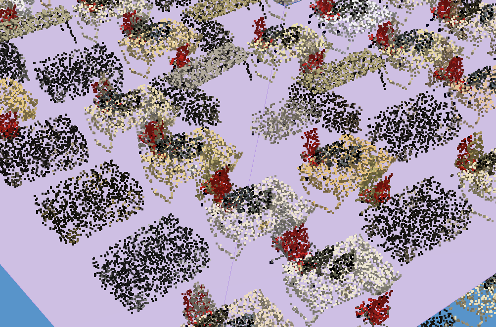
Adding Groups
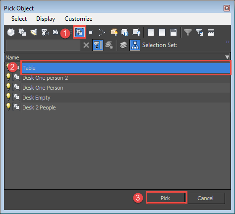
When adding groups to Forest Pack, you cannot pick them directly from the scene. Instead you can either use the Add Multiple button to select them using an object picker as describe above, or click on  to add a single object, click on Custom Object and then click
  . Next press H on the keyboard to open the Pick Object dialog, select a Group from the list and click Pick.
Adding Variety to each floor
When using the Full map type, the distribution is very dense. In this section we'll scatter a "null" object and adjust the probability vallues of the furniture to create gaps in the furniture layout.
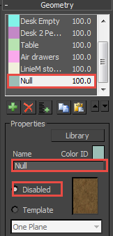
- Go to the Geometry rollout and click
![Populate Building Interiors-image2015-4-26 19:35:44.png]() to add a new item.
to add a new item. - Rename the item null and set it to Disabled
![Populate Building Interiors-image2015-4-25 16:58:39.png]()
Disabled objects do not display geometry, but still contribute to the scatter calculations, leaving a space wherever one occurs. - A few spaces have been created, but we'd like more. To do this we can adjust the probabilities of the objects. In the Items List select all the objects except Null and change the probability to 15%. Note that the values are automatically normalised, so there's no need to manually ensure they add up to 100%. You could also adjust the balance of furniture types using these setting. For example is you want fewer empty desks, just lower the Desk Empty item's probability.
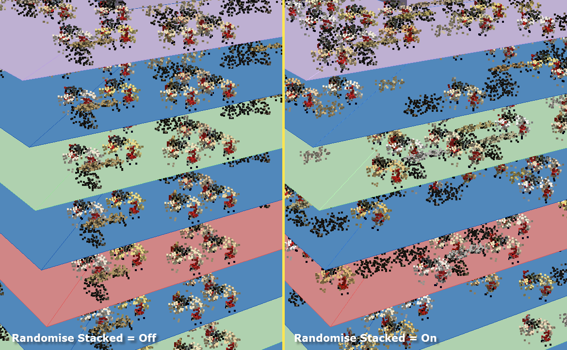
If you look at each floor, you'll notice that the objects, their distribution, and any randomised transforms are exactly the same. Fortunately this is easy to fix:
- Open the Surface rollout
- Turn on Randomise Stacked. This will randomise the transforms and scatter items on each layer. It doesn't randomise the position of the distribution map, but because we're creating spaces by using a Full map and adding a randomly placed null object we achieve a similar effect
![Populate Building Interiors-image2015-4-25 17:32:57.png]()
Preventing interpenetration with the façade
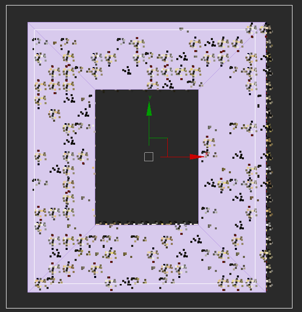
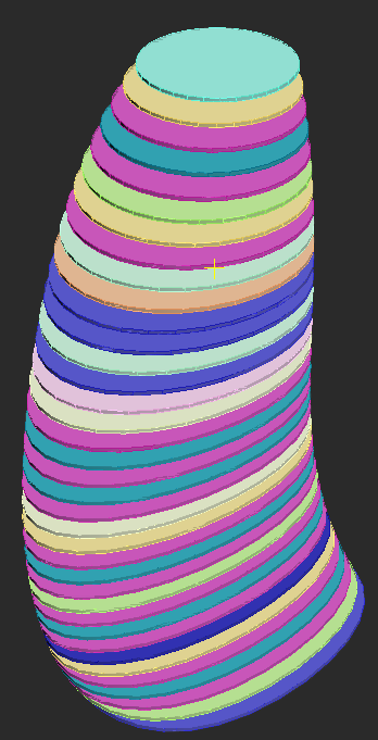
Looking at the resultant scatter from the top view, it's obvious that there are some objects that are extending beyond the edges of the floor plate.
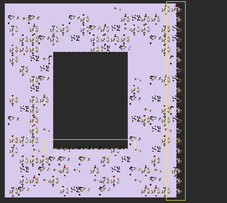
This is because Forest uses Point mode when scattering on surfaces to determine if an object should be culled. This presents a problem as these objects could extend through the façade. In this step we'll remove them using Exclude Splines.
- Create a new spline that is larger than the building in top view and convert it to an Editable Spline object.
- Go to the modify panel, and in the same spline object as created in step 1, draw a second closed spline that is smaller than the building's footprint. When we add this to Forest, items that fall between these two splines will be removed.
![Populate Building Interiors-image2015-4-25 17:43:7.png]()
- Select the Forest object and open the Areas rollout. Click
![Populate Building Interiors-image2015-4-25 17:44:23.png]() and pick the spline from the scene.
and pick the spline from the scene. - Change the mode from Include to Exclude.
![Populate Building Interiors-image2015-4-25 17:45:55.png]()
- The area between the two spline defines the exclude area. If you also want to remove objects from around the core of the building, simply add a another closed spline and set the mode to Exclude.
![Populate Building Interiors-spline area.gif]()
 and pick the spline from the scene.
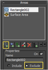
Preventing interpenetration with the Façade if the building's profile changes
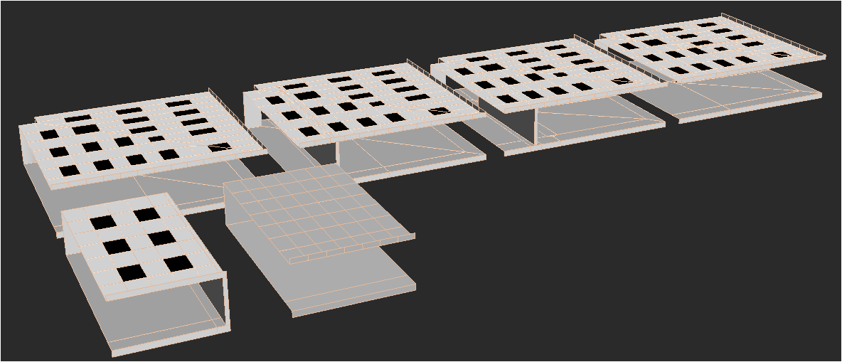
The exclude spline technique cuts through the entire height of the building, so it is ideal for structures that retain the same profile throughout their height. If there are only a couple of shape changes, then the easiest solution is probably to divide the building into multiple Forest objects, one for each new profile. But for buildings with highly variable profiles like the simplified example shown below, this would mean a lot of Forest Objects!
For this type of buildings, instead of using splines to exclude objects, we can restrict the scatter to particular material IDs. In this example we'll offset the floor plate to create a perimeter ring of polygons and change the Mat ID, but before we do that, let's apply the existing Forest Pack object to this new set of floors.
- Select the Forest object and open the Surfaces rollout.
- Delete the existing floor plates by selecting them one at a time in the Surfaces List and clicking on
![Populate Building Interiors-image2015-4-25 18:4:6.png]() .
. - To add the new plates, click on
![Populate Building Interiors-image2015-4-25 16:1:53.png]() and select the objects named Curved Plates001 to Curved Plates 037.
and select the objects named Curved Plates001 to Curved Plates 037. - To edit the plates select them all and add an Edit Poly modifier (The following few steps represent just one way of doing things, your specific geometry, texturing and job requirements may mean you need to use a different technique to assign the material IDs).
- Go to the Polygon sub-object level and select the top polygon of all the floor plates. You may find selecting with Ignore Backfacing on from the top view helps with this.
- With the polygons still selected, add another Edit Poly modifier.
- Activate the Polygon sub-object level and turn on Use Stack Selection.
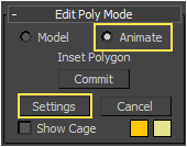
- In the Edit Poly Mode rollout, change the mode to Animate. This will allow us to come back and adjust the offset at any time.
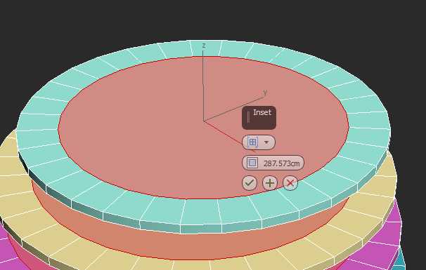
- In the Edit Geometry rollout, turn on Preserve UVs to prevent the inset operation from upsetting any existing UVW Mapping you might have set up.
- Click on the Inset Settings button and enter an inset value. Click Ok when you're done. Because we put this modifier in animate mode we can come back and change this at any time.
![Populate Building Interiors-image2015-4-25 18:15:17.png]()
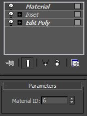
- Without deselecting the Polygons, add a new Material modifier.
- Set the Material ID value to something different from the rest of the floor plate geometry. In this example I'll use ID 6
![Populate Building Interiors-image2015-4-25 18:18:9.png]()
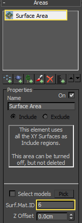
- Re-select the Forest object and open the Areas rollout.
- Delete the existing Spline Exclude area, it's not required any more.
- Select the Surface Area in the Areas list and enter the same Material ID used in step 12 above in the Surf. Mat. Id box. If necessary you can use multiple IDs, just leave a space or comma between them.
![Populate Building Interiors-image2015-4-25 18:23:37.png]()
- Remember you can go back to the Floor plates at any time to adjust the offset value. Just select the Edit Poly modifier used to create the inset, click on Settings in the Edit Poly Mode rollout and enter a new value.
![Populate Building Interiors-image2015-4-25 18:34:25.png]()
 .
.
Limiting scatters by Material IDs was introduced in Forest 4.3. It's not just useful for preventing items getting too close to the perimeter of the building. You can also use this feature to limit furniture to particular floors, rooms or even parts of rooms. You could for example have one forest object scattering desks on ID1 and another scattering filing cupboards and shelves on ID2, or you could use IDs to designate types of habitation for example ID1 = retail, ID2 = office, ID 3 = residential etc.
Scenario 2 - Floor plates are combined objects
In the previous exercise, each floor plate is a separate surface. This may not always be possible as you may have a more complex and combined mesh for the internals of a building. In this case we can use the UVW space of the surface to scatter objects.
Using UV Mode
- Use the existing Forest Pack object and go to the Areas rollout and delete the Surf. Mat. ID value.
- Go to the Surface rollout and delete the existing surfaces.
- Add a new surface by clicking
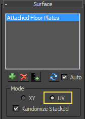
![Populate Building Interiors-image2015-4-26 19:35:44.png]() and pick Attached Floor Plates from the scene. You'll notice that when using a stack of surfaces combined into a single mesh, Forest Pack only distributes objects on the topmost polygons.
and pick Attached Floor Plates from the scene. You'll notice that when using a stack of surfaces combined into a single mesh, Forest Pack only distributes objects on the topmost polygons. - Change the Surface Mode to UVs to scatter objects on all floors.
![Populate Building Interiors-image2015-4-26 22:20:25.png]()
Adding Variety to each floor
The scatter is exactly the same on each floor, this is because the UV mapping on each floor is also identical. To add variation to the scatter when using UV mode, it is necessary for each floor's position in UV space to be slightly different. To fix this:
- Select the surface
- Apply an Unwrap UVW modifier.
- Open the UVW editor by clicking
![Populate Building Interiors-image2015-4-26 22:24:59.png]()
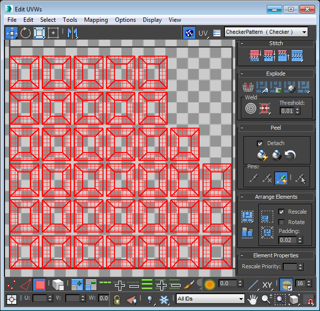
- Click
![Populate Building Interiors-image2015-4-26 22:25:21.png]() to autopack the UV islands and give each floor a unique UV space.
to autopack the UV islands and give each floor a unique UV space.
![Populate Building Interiors-image2015-4-26 22:26:8.png]()
- Each floor now has a unique distribution of objects.

 to autopack the UV islands and give each floor a unique UV space.
Preventing interpenetration with the façade
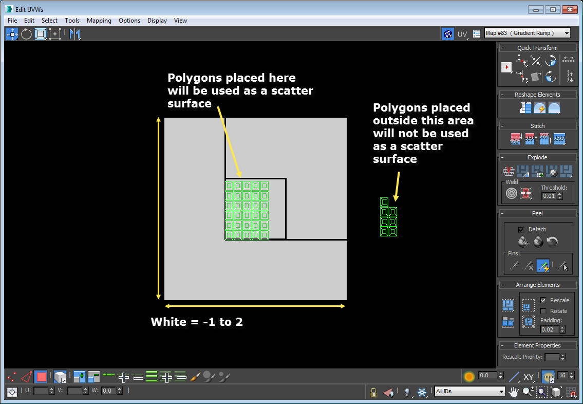
Open the Areas rollout and you'll notice that many of the features are disabled in UV mode. Consequently it is not possible to prevent scattered objects coming too close to the exterior of the building using either splines or material IDs. To achieve this in UV mode we have to be a little more inventive, and in fact the only way to really control this is using the Distribution map itself. Essentially what is required is to create a map for each floor with a white area where you want furniture and a black area where you do not. There are any number of ways these maps could be created. You could for example hand paint them using Viewport Canvas or bake them out using render to texture and Colour Edge, but the important thing is that the maps must be able to be evaluated before render time in order to work correctly. In this example I will create a white map in UV Space -1 to 2 and ensure that all polygons that should produce furniture are mapped to this area. Anywhere outside that UV space will be black, and any polygons that are not to host furniture will be moved outside this range:
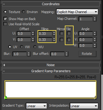
- First create the map. Select the Forest object, open the Distribution rollout and click on the Map slot. Select a Gradient Ramp and instance it to the Material Editor.
- Edit the gradient ramp so that the colour is solid white. Next turn Off Tiling so that the area outside the map is black. Enlarge the map slightly so that is occupies UV space -1 to 2 by setting the U and VTiling to 0.33.
![Populate Building Interiors-image2015-4-26 22:45:54.png]()
- We need to move any polygons that we don't want to contribute to the scatter outside this UV range. Where possible I like to try to maintain parametricism so I'll do this using a UVW XForm modifier. But first, let's add and inset to the existing surface. To do this, select the surface and add a new Edit Poly modifier.
- Go to the Polygon sub-object level and select the top polygons for all the floor plates. You may find selecting with Ignore Backfacing on from the top view helps with this.
- With the polygons still selected, add another Edit Poly modifier. If you want to remember what this is for at a later date, you could rename it to EP - Inset.
- Activate the Polygon sub-object level and turn on Use Stack Selection.
- In the Edit Poly Mode rollout, change the mode to Animate. This will allow us to come back and adjust the offset at any time.
- In the Edit Geometry rollout, turn on Preserve UVs to prevent the inset operation from upsetting any existing UVW Mapping you might have set up.
- Click on the Inset Settings button and dial in an inset value. Click Ok when you're done. Because we set this modifier to animate mode, we can come back and change this at any time.
- Without deselecting the polygons, add a third Edit Poly modifier. Go to the Polygon sub-object level and press Ctrl+I to invert the selection. If you want to remember what this modifier is for at a later date, you could rename it to EP - Invert.
- Without deselecting the polygons add a UVW XForm modifier. We can use this to move the selected polygons to a new UV space by entering a value of 5cm in the Offset property. If you're not using using Real World mapping, then 0-1 in UV space is represented by 0-1 system units. In this case the system units are in CM so we've moved the UV space of these polygons 5 UV tiles to the right.
- You will now see that the furniture has been removed from the selected polygons. Any polygon selected by the EP-Invert edit poly modifier will be passed up the stack to the UVW XForm operator and will be moved to the black area of the map. This is ideal for selecting areas of the building in which you do not want furniture to appear.
![Populate Building Interiors-image2015-4-26 23:10:58.png]()
Creating vertical zoning
Finally you may also want to limit the distribution in the building to particular floors. You could do this using the technique described above by adjusting a whole floor's UV coordinates, or alternatively you can achieve this based on the height of the building. To do this.
- Go to the Surface rollout and turn on Altitude Range > Limited.
- Set a Bottom value to determine the starting point of the scatter.
- Set a Top value to determine the end point for the scatter.
- You can then duplicate this Forest object to add different furniture on other floors, for example you might want floors 0-3 to be retail, 4 - 10 to be offices and 11+ for residential.
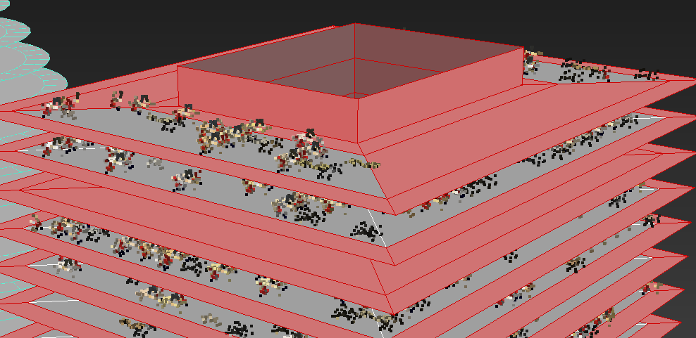
Scenario 3 - Floor plates are RailClone objects
In some cases it may be possible to use RailClone to create floor plates. When using RailClone you will have to use the UV mode as described in the previous section, but using RailClone has advantages because it allows you to parametrise the randomisation of the floor plate's UVWs to create distribution variations on each floor. This means there is no need to use the UVW unwrap modifier to manually assign each floor plate to a unique UV space.
Randomising UVWs using the XForm Operator (works with RailClone lite)
In this exercise we'll use RailClone to create a vertical array of floors. To do this:
- Create a new RailClone object.
- Go to the Style rollout and click
![Populate Building Interiors-image2015-4-27 7:31:18.png]() to open the Style Editor
to open the Style Editor - Add a new L1S generator.
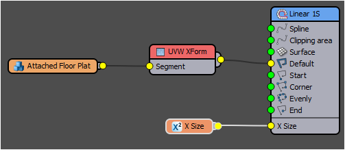
- Right click on the generator and go to Export Parameters > Geometry > X Size.
- Create a new Numeric node, change Properties > Type to Scene Units and wire it to the exported X Size property of the generator.
![Populate Building Interiors-image2015-4-27 7:36:16.png]()
- Create a new Segment node, go to its properties and pick Rectangular Floor Plate from the scene.
- Wire the Segment to the Default or Evenly input of the Generator. If you use the Evenly input you can adjust the spacing between floors using the generator's Properties > Rules > Evenly > Distance value.
- Rotate the whole RailClone object 90 degrees on the Y Axis so that the building is vertical.
- To use RailClone as a surface in Forest Pack, it's necessary to turn off the instancing engine and be sure that the full mesh displays in the viewports. To do this go to the Display rollout and turn Off Use Instancing Engine and set the Display > Viewport mode to Mesh.
- Now let's apply the furniture to this. Select the Forest Object and open the Surfaces rollout. Delete the existing surface.
- Click
![Populate Building Interiors-image2015-4-26 19:35:44.png]() to add a new surface and select the RailClone object. The mode is already set to UV so we don't need to change anything here. You'll notice that the distribution is the same for each floor, as in Scenario 2, this is because each floor shares the same UVW space. Let's fix this in RailClone.
to add a new surface and select the RailClone object. The mode is already set to UV so we don't need to change anything here. You'll notice that the distribution is the same for each floor, as in Scenario 2, this is because each floor shares the same UVW space. Let's fix this in RailClone. - Select the RailClone object and open the Style Editor.
- Add a new UVW XForm node and wire it between the existing segment and the generator.
![Populate Building Interiors-image2015-4-27 7:56:26.png]()
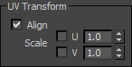
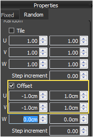
- Go to the UVW XForm node's Properties and turn on Random > Offset.
- Enter a value of -1cm for the U and VMin and 1cm for the Max. As with the UVW modifier, 1 scene unit equals 1 UV unit. By using these values we're ensuring that the randomisation keeps the UVs within the white area of the map that we created earlier in the tutorial.
- You should now see that the distribution is randomised on each floor! If you change the X Size parameter of the RailClone object you can add additional floors and the Forest object will update automatically.
 to open the Style Editor
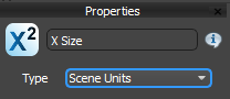
Preventing interpenetration with the façade
We're using UV mode, so the best way to control the scatter is still using the distribution map as described earlier. The only real difference is that we only need to edit a single floor mesh, because RailClone will duplicate the geometry on every level. This also explains why we make the white area of the distribution map extend slightly beyond 0 -1 UV space. If we didn't the UVW XForm randomisation effect could cause unwanted black areas to appear in the distribution map.
Use UVWs to control the rotation of objects
If you look closely at the alignment of the desks in relation to the building perimeter, you'll notice that they are all facing the same way, irrespective of which side of the building they are on. Ideally we'd like the desks to rotate to remain in the same alignment in relation to the building's footprint. We can't use the transform by map settings for this because the desk, chairs and computer are grouped, so they'll only rotate around their ownlocal axis. Luckily though, we can achieve this effect by aligning the scattered objects using the surfaces UVs. Here's how:
- UV Align can be found in the surfaces rollout. It's on by default but you can change it from here if you want to turn it on or off.
![Populate Building Interiors-image2015-4-27 7:53:38.png]()
- Select the floor plate source geometry called Rectangular Floor Plate.
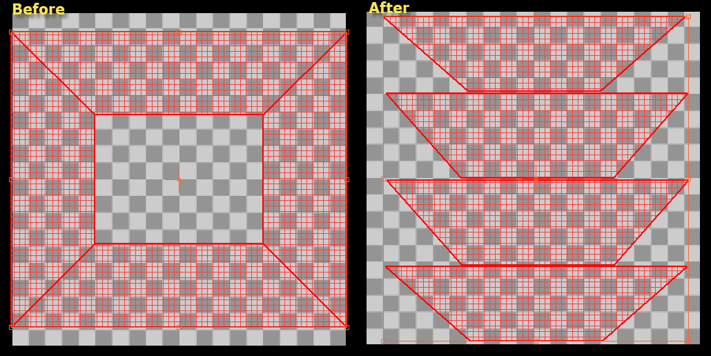
- Select the existing Unwrap UVW modifier in the stack and open the UV Editor. We need to make the outside face of the building align with the U axis. To do this detach each side and rotate it so that it look like this.
![Populate Building Interiors-image2015-4-27 8:15:43.png]()
- If you look at the desks now you'll notice that they remain aligned with the exterior face of the building. if you swap the rectilinear floor for the circular one, you can see this effect more clearly.
Creating the RailClone interior, an alternative approach (Compatible with RailClone Lite)
In this example, instead of using RailClone to create a stack of surfaces, we can use it to add a 2 dimensional array of rooms around the perimeter of the building. This style uses two room models -one with and one without a wall - and 4 corner segments with different internal wall configurations. The more of these you add the greater variation you can achieve inside the building.
The rooms have already been mapped so that the perimeter's UVW are moved to the black area of the existing distribution map using the technique described above. In addition there's a V-Ray light material on the ceiling that we can randomise in RailClone to turn lights on and off. Let's use these objects and create a new style:
- Create a new RailClone object. Go to the Display rollout and set the Viewport Mode to Mesh and turn off Use Instancing Engine.
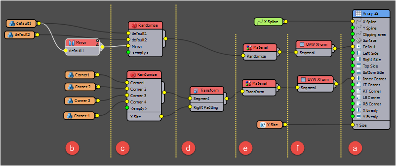
- Open the Style editor. We're going to create a new node graph with the following features:
![Populate Building Interiors-image2015-4-27 9:9:28.png]()
- An A2S Generator allows us to create a 2D array. The building footprint defines the X axis and the building's height defines the Y Axis.
- A number of "room" Segments. This example only uses a few but you could add more for greater variety.
- Randomise operators select from the room segments at random.
- The Transform operator adds padding to the corner segments to make the corners work correctly.
- Material operators randomise the ceiling material to turn lights on and off
- UVW XForm operators randomise the UVs to create variation in the Forest Pack scatter for each segment.
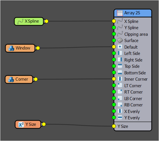
- To create this, start with a new A2S Generator and set the X Rotation value to 90 degrees. This rotates the array's Y axis so that it is aligned with the world's Z axis.
- Go to the generator's Properties > Rules > X Corner group and set Bevel Mode to None. This will prevent the corner geometry from being sliced. Turn of Align to Path so that the corners align with the preceding spline segment.
- Add a new Spline node and select building_spline from the scene. Wire the node to the Generator's X Spline input.
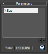
- Export the generator's Y Size parameter and wire it to a new Numeric node. Change the numeric node type to Scene Units and enter a value of 12000.0cm.
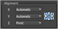
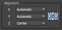
- Now we'll add some segments. Create two new segment nodes and change the Properties > Alignment > Z value to Pivot.
![Populate Building Interiors-image2015-4-27 9:24:39.png]()
- Select the segment nodes, open the Properties and pick the rooms named Default1 and Default2 from the scene.
- Wire the the segment nodes to a new Randomize operator. To add more variety you could also add a Mirror operator, wire it to the randomise operator, then to the default1 segment to created a flipped version of that room.
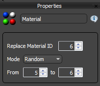
- Wire the Randomise operator to a new Material operator. Set the Material node's Properties as shown below.
![Populate Building Interiors-image2015-4-27 9:37:44.png]()
For all the polygons with a Material ID of 6, this operator is randomising them between ID 5 which allocates a material with the lights switched off, and ID 6 which contains a material with the lights turned on. - Wire the Material node to a new UVW XForm operator. To randomise distribution, set the XForm node's properties as in the image below.
![Populate Building Interiors-image2015-4-27 9:41:52.png]()
- Now wire the UVW XForm operator to the Generator's default input. Next we'll add the corners.
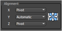
- Create four new Segment nodes and change the Properties > Alignment > X & Z value to Pivot. (Lite users are restricted to using up to 3 segments per style so will only be able to add a single corner segment)
![Populate Building Interiors-image2015-4-27 9:24:39.png]()
- Use these segments to pick Corner1, Corner2, Corner3, and Corner4 from the scene.
- Wire these to a new Randomise operator.
- Duplicate the existing Material and UVW XForm operators and wire them to the Randomise operator and the Generator's Corner input.
- If you look at the corner you'll see there is a problem with overlapping segments. To resolve this we need to add Right Padding to the Corner segments. Add a new Transform operator between the Randomise and the Material nodes.
- Right click on the node and export the parameter Padding > Right Padding.
- Right click on the corner's randomise node and export the attribute Size > X.
- Wire the X Size attribute to the Right Padding parameter. The Corner's right padding is now exactly the same size as it's dimension on the X axis!
- This completes the building interior. We can now apply the Forest Pack object to it. Select the furniture Forest Pack object and open the Surface rollout. Delete the existing surface and add the new RailClone object instead.
- You'll notice that objects are being scattered on the ceilings and walls. To prevent this we need to limit the scatter to only those polygons which are facing upwards. You can do this using the Limit to Slope controls in the Surface rollout. Turn on Slope Range > Limited and enter a Max value of 5.
You can now use the same technique to add some people. To do this;
- Duplicate the existing Forest Pack, go to the Geometry rollout and delete all the items except Null.
- Click on Add Multiple and pick the Male and Female characters. Adjust their probability until you get the desired distribution. A low value of 2% or 3% works well.
- Because we duplicated the existing furniture Forest Pack object, they share the same distribution points. This results in characters stood in the middle of desks. To move the grid so that the characters stand between the furniture we can use the Transform > Translate feature. Open the Transform rollout, enable Translation and enter Min and Max value of -30 (or until the grid is adequately offset). You could also turn on Rotation randomisation to add a little more variety.
We've now populated the interior of this building with people and furniture. Moreover this entire set-up is fully parametric. If we change the size of the base spline, the rooms, furniture and people all update automatically!
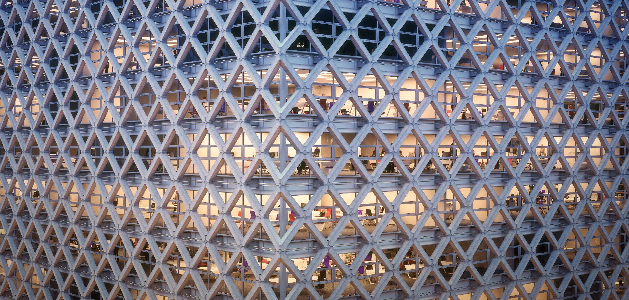
Bonus! - Creating the Façade with RailClone (Lite)
To round up this tutorial, let's create a couple of RailClone styles to add a façade to this building. To maintain compatibility with the Lite version we'll split the facade into 2 separate RailClone objects but they could easily be combined if you are a Pro user.
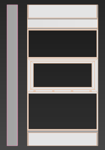
This styles each use two segments. For the windows, a corner and the window itself:
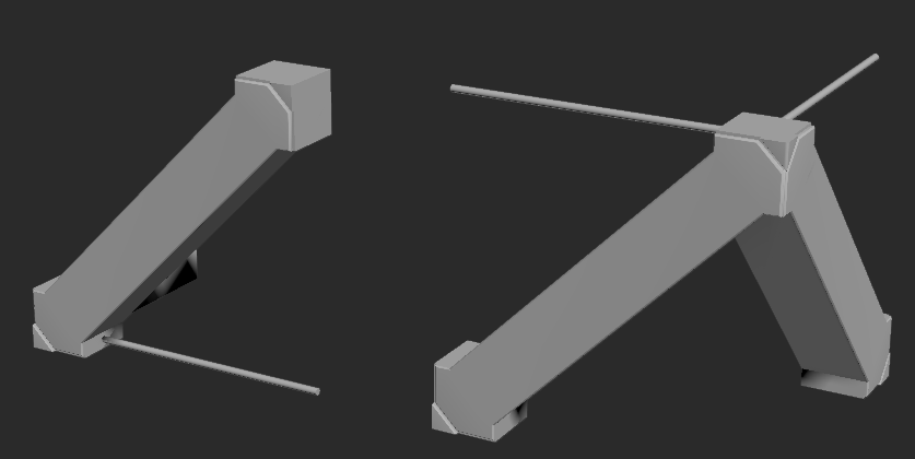
And for the support bracing, a single diagonal and a corner:
The aim with these styles is to maintain instancing support as much as possible. To ensure this, none of the segments are sliced or bent and the Corner segments have been pre-sliced before adding them to RailClone. Here's how to construct these styles.
Creating the Window style
- Create a new RailClone object. Go to the Display rollout and temporarily set the Viewport Mode to Mesh. This is just while we create the style, when it's used on the whole building we will need to set this to Adaptive mode to ensure viewport performance is not affected by the millions of polygons RailClone can create.
- Open the Style Editor. We're going to create a new graph that looks like this.
![Populate Building Interiors-image2015-4-27 11:33:6.png]()
As you can see this is a relatively simple style. - To create this, start with a new A2S array and set the X Rotation value to 90 degrees. This rotates the array's Y axis so that it is aligned with the world's Z axis.
- Go to the generator's Properties > Rules and set the default mode to Adaptive. This will mean that only whole segments are used and RailClone will only add an additional window where there is sufficient space to do so. All the windows will be subtly scaled to fill the available space without leaving gaps.
- In the Properties > Rules > X Corner group, Turn of Align to Path so that the corners align with the preceding spline segment.
- Add a new Spline node and select building_spline from the scene. Wire the node to the generator's X Spline input.
- Export the generator's Y Size parameter and wire it to a new Numeric node. Change the Numeric node's type to Scene Units and enter a value of 350.0cm. We Will increase this value to the full height of the building once the style is completed but it's helpful to use a smaller value while we create the style to keep the geometry responsive.
- Now we'll add some segments. Create two new Segment nodes and change the Properties > Alignment > Z value to Center.
![Populate Building Interiors-image2015-4-27 11:38:17.png]()
- For each segment, turn off Properties > Deform > Bend and Slice.
- Use these two segments to pick the objects named facade_corner and facade_window from the scene.
- Wire the facade_window segment to the generator's Default input and wire the facade_corner segment to the Corner input.
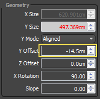
- Finally, offset the whole style so that window moves outside of the floor plates by entering -14.5cm for the Generator'sProperties > Y Offset value.
![Populate Building Interiors-image2015-4-27 11:44:13.png]()
Creating the Diagonal Braces
To create the diagonal braces we'll use the same technique, but with the addition of mirror and sequence nodes to re-use a single diagonal component and create a diamond pattern. To do this:
- Clone the Windows RailClone object, rename it Diagonals and open the Style Editor.
- Select the Window Segment and change the geometry by picking diagonal_default from the scene. Change Properties > Alignment > Z to Pivot
- Select the Corner Segment and change the geometry by picking diagonal_corner from the scene. Change Properties > Alignment > Z and X to Pivot. The pivots on the source objects have been moved so that the segments will align correctly, changing these options ensures RailClone uses them.
![Populate Building Interiors-image2015-4-27 11:58:37.png]()
- Change the generator's Y Offset value to -103cm.
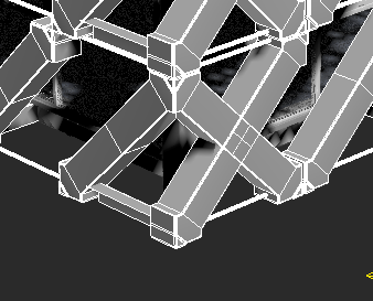
- The corner has an overlapping issue:
![Populate Building Interiors-image2015-4-27 12:4:43.png]()
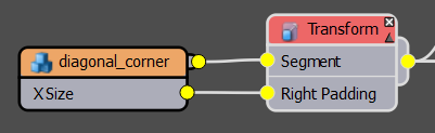
We can fix this by adding some padding to the right of the corner segment. We'll use the size of the segment on the X axis and add this value to the Right padding. To do this, right click on the corner Segment and export the X Size attribute. Next add a new Transform operator between the Segment and the Generator and export its Right Padding parameter. Wire the Segment's X Size attribute to the Transform operator's Right Padding parameter. Finally, go to the Transform operator's properties and activate Padding.![Populate Building Interiors-image2015-4-27 12:8:53.png]()
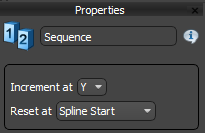
- To create the diamond pattern in the corners, wire a new Sequence operator between the Transform operator and the generator's Inner Corner input. Select the Sequence operator, open the properties and set it to Increment at Y.
![Populate Building Interiors-image2015-4-27 12:11:25.png]()
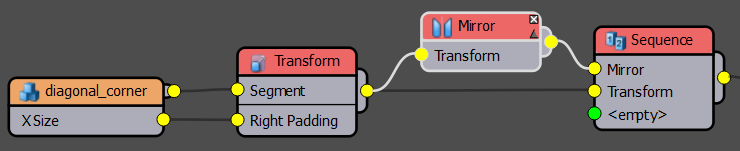
- Wire a Mirror operator between the Corner Segment and the Sequence operator. Change the Mirror Axis to Y.
![Populate Building Interiors-image2015-4-27 12:14:45.png]()
- Wire the Corner Segment directly to the Sequence node, bypassing the Mirror operator.
![Populate Building Interiors-image2015-4-27 12:15:32.png]()
- That's the corner finished. Now lets create the same sort of pattern for the Default segment. Wire a new Sequence operator between the Default Segment and the Generator's Default Input.
- Wire the Default node to the second input of the Sequence operator via a new Mirror node.
- Create a second Sequence operator and wire the existing Sequence node to its first input. Change the new Sequence operator to Increment at Y.
- Wire the original sequence node to the second input of the new Sequence operator via a new Mirror node. Set the Mirror axis to Y. You should now have a diamond pattern!
To finish up we'll restore the full height of the building. Before you do this make sure you go to the display rollout for both RailClone objects and set the Viewport Mode to Adaptive. You can then set the height of the building in the Parameters rollout found in the ModifyPanel.
Once this is done, you're ready to render!
Conclusion
In this tutorial we covered a number of useful techniques for scattering objects onto stacked surfaces. Although the focus was populating the inside of buildings, it is our hope that some of these tricks will find usage in a much wider range of applications. If you have an interesting project please feel free to share it on our forum and stay tuned for even more Forest Pack and RailClone training coming soon. For more information about the features demonstrated in this tutorial, check out our reference section or visit the tutorials page for more Tips & Tricks videos and in-depth tutorials.