Resources
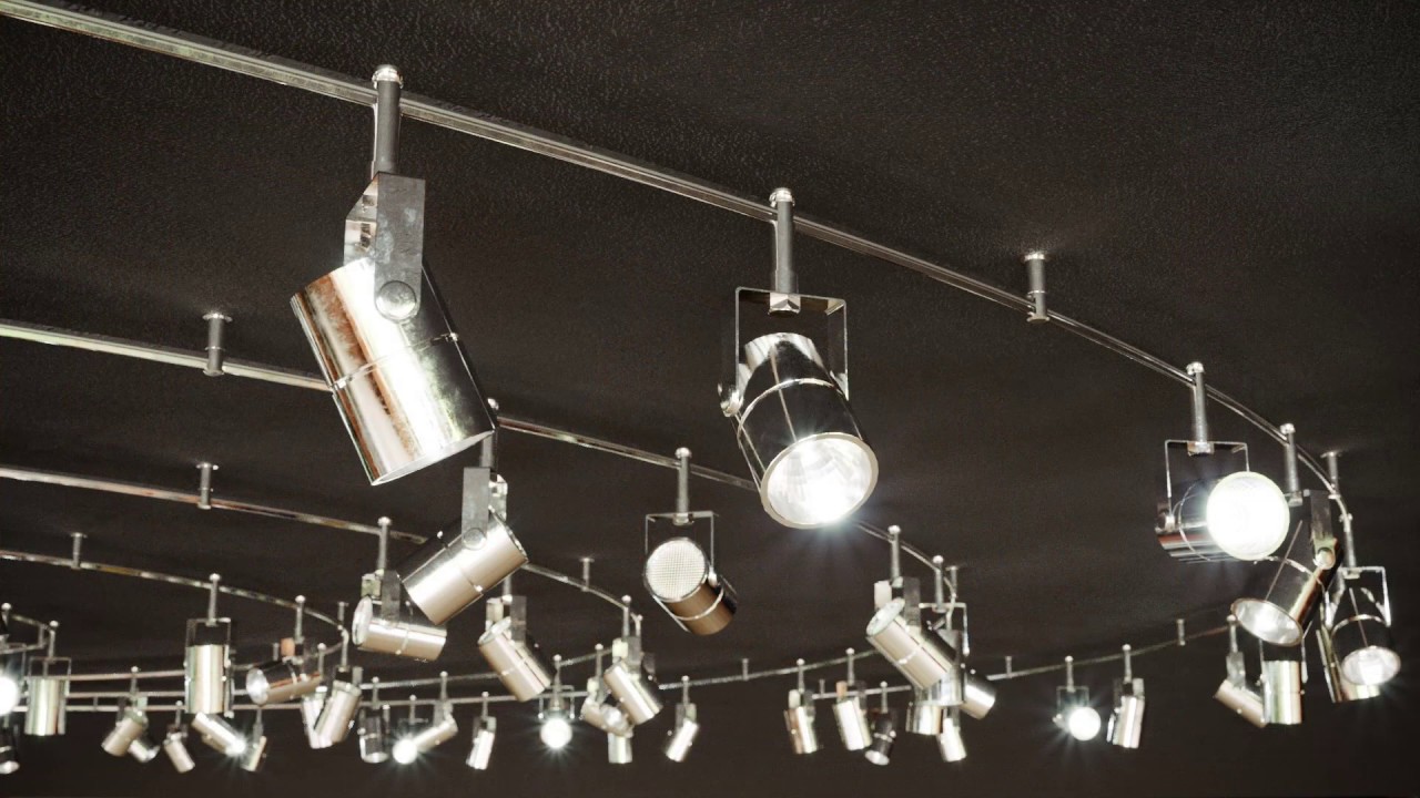
In this tutorial we demonstrate how to create adjustable track lighting with RailClone 4 and above. The first part of this tutorial can be completed with the free Lite version, but for the more advanced version you will need RailClone Pro. This tutorial only deals with geometry. It is not yet possible to distribute lights with RailClone … yet.
To get started you’ll need some base geometry. This isn’t a modelling tutorial so we won’t explain that process, but it’s helpful to understand how many pieces you should split a model like this into, and why.
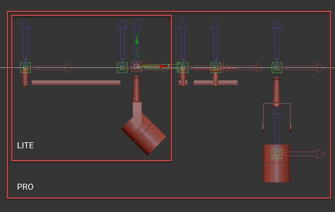
Where possible, think about dividing any design into smaller, more manageable sections. In this example, I planned the rail section and the light itself separately. The rail could consist of as few as two pieces: one bracket piece and the metallic strip. To make sure that this all aligns correctly once added to RailClone, the pivots for both pieces should be aligned at ceiling level. If you are using RailClone Pro you could optionally use two additional pieces for the start and the end since you will be able to use more segments
For the light fitting, in RailClone Lite you will use a single object. This will allow you to randomise the rotation on the Z-axis, but the other angles are fixed. If you are using RailClone Pro you can split the light into two parts: A top section that connects to the rail and can rotate on the Z-axis, and a separate light so it can be rotated on the other axis. The first of these segments has had its pivot adjusted so it’s connected to the rail. The light itself has its pivot aligned to the position we would like it to rotate around.
Let’s assemble these pieces into a style, starting with a version that’s compatible with RailClone Lite.
- Create a new RailClone object and open the Style Editor.
- Create a new L1S Generator.
- Add a Spline node and select a spline from the scene.
- Wire the Spline node to the Spline input.
- Now let’s import the geometry. Create a single Segment node. Right-click on it and choose Clone Multiple. Select the objects and click Clone. This is a nice fast way to import a lot of things quickly.
![Clone mutlple]()
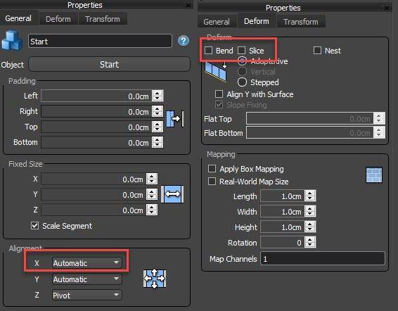
- Wire the Bracket Segment to the Start, End, and Evenly inputs. Change the Alignment > Z option to Pivot so it sits below the spline. Turn off Bend and Slice. The only segment that should bend in this style is the rail itself
![Segment Settings]()
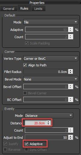
- To adjust the spacing of these you use the Rules> Evenly > Distance parameter. To ensure all the spaces are the same size, turn on Adaptive (without this the first and last spaces are averaged and the remaining ones are exactly the value in the Distance property).
![Evenly Settings]()
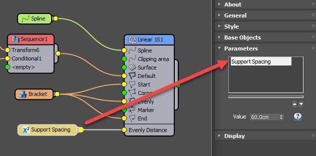
- To make this style easier for people to use, right-click on the Generator and export Evenly Distance.
Attach a new Numeric node and change the type to Scene Units. This property can now be controlled from the Modify panel. This is ideal when creating styles that you want other artists to use, or if you simply don’t want to open the graph every time you need to make a small change. Nearly any parameter can be exported in this way.![Numeric]()
- Wire the Rail segment to the Default input. The geometry in this input essentially fills along the spline anywhere that is left after the geometry in the other inputs has been applied. As you can see we need to change the Z Alignment to Pivot so that it snaps together correctly.
- You will notice that the Rail geometry stops short of the brackets. This is because RailClone uses the bounding box of the geometry to calculate adjacencies. There are a few ways we could fix this, but in this example, we will simply tell RailClone that this segment is much smaller than it actually is. To do that, go to the Bracket segment and enter a very small value for Fixed Size > X. This will flatten the geometry. By disabling Scale Segment, instead only the bounding box used to calculate adjacent segments is scaled, the actual geometry is unaffected.
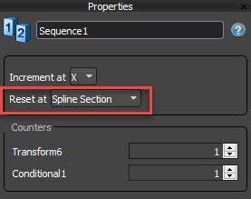
- Select the Light Whole segment, disable Bend and Slice and change X,Y and Z Alignment to Pivot. To add this we will also need to use the Default input, since we want it between the Evenly segments, so let’s create an alternating pattern of Rail then Light using a Sequence operator. Wire it to the Default input and wire the Rail segment to its first input. Next wire the Light segment to the second input. Change the Sequence operator’s mode so that it resets after each Evenly segment by selecting Reset at Spline Section. Finally, set the Fixed size to a small value and disable Scale Segment to force the rail to continue to the centre of the light.
![Sequence settings]()
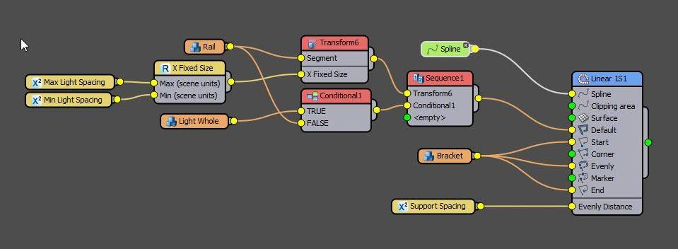
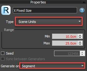
- So far so good, but the spacing is too regular. To fix this we can randomise the length of the Rail segment. Add a Transform operator between the Rail segment and the Sequence operator. Turn on Fixed Size, right-click on the Transform node and export X Fixed Size.
- Wire a Random number node to this newly exported input, change the mode to Scene Units and adjust the Minimum and Maximum value. Change Generate On to Segment
![Generate On]()
- These are two other settings we might want to change regularly, so we can expose them in the Modify panel just like we did for the Evenly Distance. Right-click on the Transform node and Export Min and Max Scene Units.
- Create two new Number nodes and wire one to each of the new inputs. Don’t forget to rename them so it’s clear what they do.
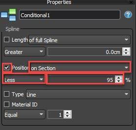
- So far, so good, but there are some occasions when you might get overlapping segments. To fix that, wire a Conditional node after the Light segment and wire the Light to the True input. Wire the Rail to the second input. You can now change the Conditional node’s settings so that it only returns True (the light) if it is less than 95% of the way along the current spline section.
![Conditional-settings]()
- Finally, select the Light segment and enable Transform>Random>Rotation. For the Z-Axis enter -180 Min and 180 Max.

That concludes the Lite version of the lighting style. You will now have an object that can be applied to any number of splines. It has adjustable spacing for the lights and the support with randomised light direction. That’s pretty cool and if that’s all you need you can stop here - but if you have RailClone Pro you can take it a little further and randomise the rotation of the light on the Y-axis as well as the Z, plus use different start and end pieces.
- First of all, import the alternate Start and End pieces. Set Alignment>Z to Pivot and wire them to the Start and End inputs as appropriate.
- Delete the existing Light Whole segment.
- Wire a Compose operator to the True input of the Conditional operator. Change its mode to Grouped. This mode will align the segments based on their pivot points rather than bounding boxes.
- Wire the Light Bracket and Light segments to the Compose operator.
- Now let’s add some randomisation. Wire a Transform operator after the Light Bracket segment. Right-click and expose Z Fixed Rotation.
- Attach a Randomnumber node, set its Type to Float and set Min -180 and Max to 180.Change Generate On to Segment
- Duplicate the Transform operator and attach it after the Light segment. Both will now be rotating together but the Light segment is in the wrong place. Move it into position by changing the Fixed Z Translation value.
- Create another Transform node and wire it immediately after the Light segment and before the existing Transform operator. You can now use the Fixed Y Rotation property to angle the lights.
- Let's randomise this value by exporting it and attaching a Random number node. Set the type to Float and use a Min value of -90 and a Max value of 90. Set Generate On to Segment
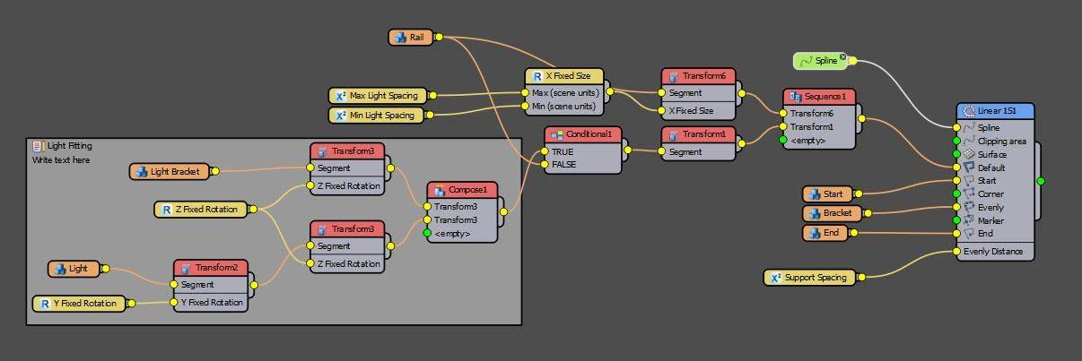
- The way to think about this sequence of Transform operators in RailClone 4 is to imagine processing them backwards. First, we randomise the rotation on the Z-axis, afterwards we randomise rotation on the Y. If this order was reversed you wouldn’t get the desired results.
![Transform order]()
- Finally, we need to fix the alignment and the gap in the rails. To do that, wire a new Transform node after the Compose operator. Set the Alignment for all axes to Pivot and change the Fixed Size to a very small number - just like we did earlier in this tutorial.

That’s it. In this tutorial, we looked at two ways of creating track lighting. Many of the principles explored in this video can also be used in many other types of object. Remember if you’ve got a question you’d like to see explained in a short tutorial, just let us know on the forum. Thanks, and stay tuned for more coming soon!