Resources
Requirements
- info RailClone Pro
Introduction
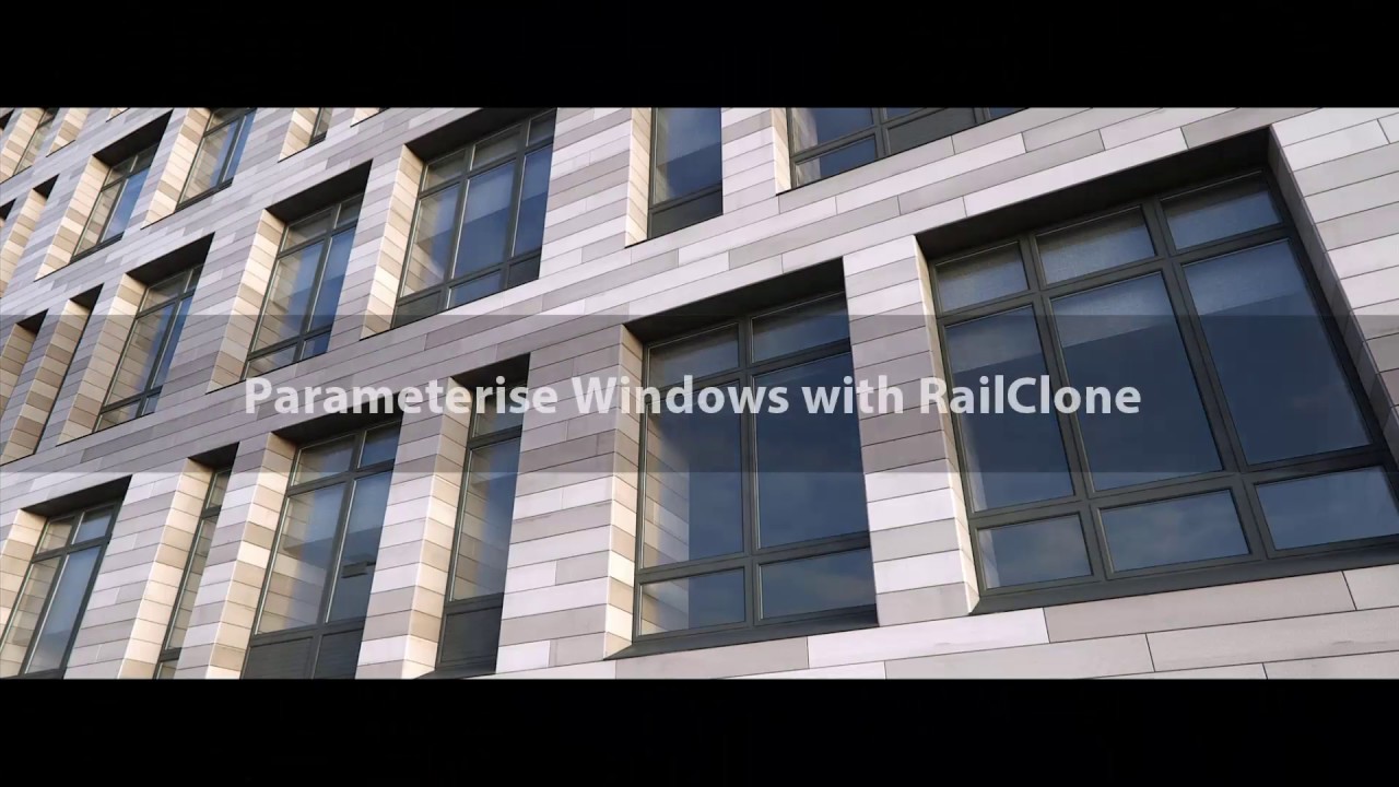
In one of our previous demo reels there was a brief clip showing a parameterised window model. Since this was released we've been asked a number of times about the best way to create this kind of object. To answer those questions this tips and tricks episode will look at the best way to prepare a window model and parametrise it using RailClone so that it can be easily re-used in in different sizes. Once we've gone through the process of creating this object, we'll also show how you can automatically fill an entire façade with windows in a single click.
Once you understand how RailClone works, creating these styles is very straightforward but actually you should only need to do it once. To create different window styles all you need to do is swap the source geometry, there's no need to go through this full procedure each time.
By completing this tutorial you will be able to:
- Prepare models for use with an A2S array.
- Create windows models with editable height, width, and horizontal and vertical divisions
- Use the Selector operator with an Expression to change segments based on their position in the array.
- Create patterns using the Sequence operator.
- Use Clipping splines to set the dimensions of an array
Download Contents
The exercise files for this tutorial includes the following .max scenes compatible with Max 2010 and includes materials for Mental Ray and V-Ray.
- parameterising_windows_start.max The starting file if you want to follow the tutorial.
- parameterising_windows_end.max The result of the completed tutorial.
Preparing Geometry
This tutorial starts from a single complete window object, shown below.
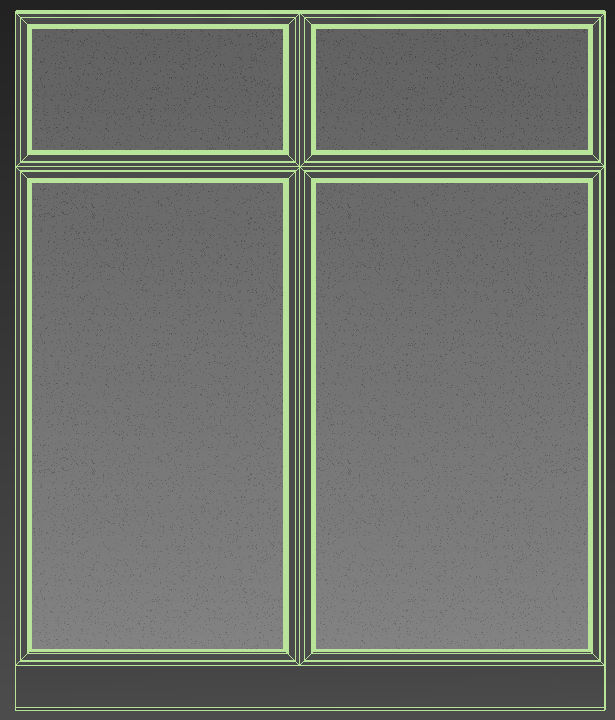
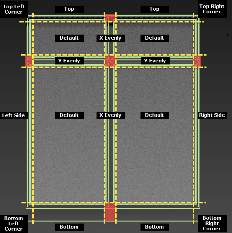
To parametrise this geometry we need to slice this mesh into a 2d grid of separate pieces that fits back together like a jigsaw using one of RailClone's array types. Because we want to adjust the height and the width of the window, we'll use the A2S generator which has the following inputs:
- Bottom Left Corner
- Bottom Right Corner
- Top Left Corner
- Top Right Corner
- Left Side
- Right Side
- Bottom Side
- Top Side
- X Evenly
- Y Evenly
- Default
To split the geometry to fit into these inputs we use 8 Slice modifiers. The position of the slice planes is marked in yellow in the image below, there are 4 needed for each Axis. Also in this image are the segments that these slices will create with their associated inputs in an A2S generator. The segments highlighted in red don't have an equivalent generator input, but we'll see later how you can get around this limitation.
To create these slice planes, follow these steps:
- Add a new Slice modifier to the window object and rotate the slice plane by 90 degrees on the Y axis. Move the slice plane on the X Axis so that it is just inside the left frame (for guidance, see the dashed yellow lines on the diagram above). Rename this slice modifier Slice Left.
- Copy and Paste the Slice modifier and rename it Slice Right. Move the slice plane on the X Axis so that it's just inside the right jamb .
- Copy and Paste the Slice modifier and rename it Slice X Evenly 1. Move the slice plane on the X Axis so that it's to the left of the the mullion.
- Copy and Paste the Slice modifier and rename it Slice X Evenly 2. Move the slice plane on the X Axis so that it's to the right of the mullion. Now that we've created all the vertical slice planes we can create the horizontals.
- Add another new Slice modifier and rotate the slice plane by -90 degrees on the X axis. Move the slice plane on the Y Axis so that it is just above Sill. Rename this slice modifier Slice Bottom.
- Copy and Paste this new modifier and rename it Slice Top. Move the slice plane on the Y axis to that it's just below the head.
- Paste a new Slice modifier and rename it Slice Y Evenly 1. Move the slice plane on the Y axis to that it's just below the transom.
- Paste a new Slice modifier and rename it Slice Y Evenly 2. Move the slice plane on the Y axis to that it's just above the transom.
- You will now have 8 slice modifier as shown below:
![Parameterising Windows-slices.gif]()
We can now toggle the Slice type of these modifiers to create the segments needed to create a parametric window.
- We'll start with the bottom row, so set the Slice Bottom modifier to Slice Type > Remove Top.
- To create the Bottom Corners segment, set the Slice Left modifier to Remove Bottom. After you've changed the slice modifiers to create each segment either Clone it with Control + V or use the Snapshot tool to create a mesh copy
- To create the Bottom segment, set the Slice Left modifier to Remove Top and the Slice X Evenly 1 modifier to Remove Bottom. Create a copy
- To create the X Evenly Bottom segment, set the Slice X Evenly 1 modifier to Remove Top and theSlice X Evenly 2 modifier to Remove Bottom. Create a copy. That's the first row done. There's no need to create the right half of the window because it is a mirrored repeat of the left side.
- To do the second row we just need to adjust the horizontal slices and then repeat the same steps. So change the Slice Bottom modifier type to Remove Bottom and change the Slice Y Evenly 1 modifier's type to Remove Top. Now we can create the second row.
- To create the Left segment, set the Slice Left modifier to Remove Bottom. Create a copy
- To create the Default segment, set the Slice Left modifier to Remove Top and the Slice X Evenly 1 modifier to Remove Bottom. Create a copy
- To create the X Evenly segment, set the Slice X Evenly 1 modifier to Remove Top and theSlice X Evenly 2 modifier to Remove Bottom. Create a copy. That's the second row done.
- Next we'll do the Transom row. To isolate this row, set Slice Y Evenly 1 to Remove Bottom and Slice Y Evenly 2 to Remove Top. The other two horizontal slice modifiers can be disabled for now.
- To create the LeftY Evenly segment, set the Slice Left modifier to Remove Bottom. Create a copy
- To create the DefaultY Evenly segment, set the Slice Left modifier to Remove Top and the Slice X Evenly 1 modifier to Remove Bottom. Create a copy
- To create the Evenly Junction segment, set the Slice X Evenly 1 modifier to Remove Top and theSlice X Evenly 2 modifier to Remove Bottom. Create a copy. Finally we'll create the top of the array
- Disable the two Y Evenly Slice operators and enable Slice Top. Set the slice type to Remove Bottom
- To create the Top Corners segment, set the Slice Left modifier to Remove Bottom. Create a copy
- To create the Top segment, set the Slice Left modifier to Remove Top and the Slice X Evenly 1 modifier to Remove Bottom. Create a copy
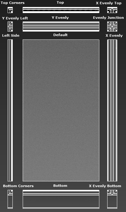
- To create theX Evenly Top segment, set the Slice X Evenly 1 modifier to Remove Top and theSlice X Evenly 2 modifier to Remove Bottom. You now have all the pieces you need to create this style.Once the slicing procedure is completed you should be left with 12 jigsaw pieces ready to be added to a new RailClone object! In this tutorial we'll refer to the pieces using the names shown in the illustration below.
![Parameterising Windows-image2015-11-20 17:4:42.png]()
Because this process can be a bit tedious we have a script we use internally called RailClone slicer. It allows you to create and control all the necessary slice planes from a single interface to prepare models for both 1D and 2D arrays. To use it just adjust the spinners to places the slice planes and when you're done you can click the Slice Geometry button to create and name all the individual pieces. If you'd like to try it out you can download the maxscript file below, or find out more about the script on our forum.
Creating the Windows
With the geometry prepared we can now add them to a RailClone object.
Standard Inputs
- Create a rectangular spline in the scene the size of a typical window.
- Create a new RailClone object and open the Style Editor.
- Drag an A2S generator from the Items list to the Construction View.
- We're going to set the size of this array using a closed spline. To do this you need to create a new Spline node and wire it to the generator's Clipping Spline input.
- In the spline node's properties, pick the Spline created in step 1.
- To tell RailClone to use this spline to determine the size of the array, select the Generator and turn on Properties > Rules > Clipping Area > Extend X/Y Size to Area.
- To scale the default segments on the X axis, open the Properties and change Rules > Default Segment > Mode from tile to Scale. This will minimise the number of segments that are created.
- That's the array set up, we're ready to start adding segments. Create a new Segment node and set Alignment > Z to Pivot. We'll do this for all the segments from now on to ensure they all align correctly. Click
![Parameterising Windows-image2015-11-18 18:9:57.png]() and select the bottoms corners geometry from the scene.
and select the bottoms corners geometry from the scene. - Wire this segment to the Generator's LB Corner input.
- To create the bottom right corner, add a new Mirror operator and wire it to the Generator's RB Corner input. Wire the corner Segment to the Mirror operator's input.
![Parameterising Windows-image2015-11-18 18:14:3.png]()
- Copy and Paste the existing segment to save time changing the Alignment mode, and use it to pick the Bottom geometry from the scene. Wire this segment to the Generator's Bottom input.
- Next we'll add the left and right side. Duplicate one of the existing Segments and use it to pick the Left Side geometry from the scene. Wire this to the Left input.
- Wire the Left Segment to the Generator's Right input via a Mirror operator.
- Paste another segment and pick the Default geometry. Wire this to the Default input.
- Now we'll add the top row. Paste another segment node and pick the Top Corners geometry. Wire this to the Generator's LT Corner input.
- To create the top right corner, add a new Mirror operator and wire it to the Generator's RT Corner input. Wire the Top Corners Segment to the Mirror operator's input.
- Duplicate a Segment and pick to Top geometry. Wire this to the Generator's Top input.
- You'll now have a window with a frame around the perimeter. You can adjust the size by simply editing the spline. You're graph should look like the image below.
![Parameterising Windows-image2015-11-20 17:20:2.png]()
 and select the bottoms corners geometry from the scene.
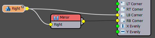
X Evenly columns - Extending inputs
With a simple window done we can add the divisions, starting with the mullions. To do this we need to add start and end segments for the X Evenly Column in the top and bottom rows. Unfortunately the generator has no inputs for this purpose but It is possible to create this effect using a selector operator and a simple expression:
- Create a new Selector operator and wire it to the generator's X Evenly input.
- Duplicate a Segment node and pick the X Evenly Top object from the scene. Wire this to the Selector operator's first input.
- Duplicate a Segment node and pick the X Evenly object from the scene. Wire this to the Selector operator's second input.
- Duplicate a Segment node and pick the X EvenlyBottom object from the scene. Wire this to the Selector operator's third input.
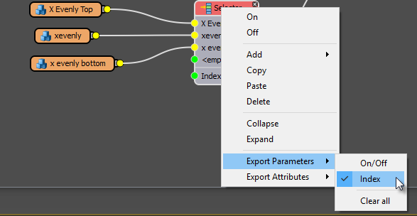
- The selector operator has an Index parameter that determines which of the segments wired to its inputs is used. If we right click on the generator and Export this property we can control which segment is used programmatically using an Arithmetic node.
![Parameterising Windows-image2015-11-20 17:43:11.png]()
- Create a new Arithmetic node and wire it to Selector operator's exported Index input.
- Change the Arithmetic node's operation to Expression and click Edit Expression to open the Style Editor.
We are going to create a conditional expression that uses the segment's position on the Y axis of the array to change the Selector Node's index. This will use one type of function and one variable.
Function
if(p,q,r)
This conditional function tests to see if the result of a boolean comparison (p) is true. If it's true it outputs the value q or if it's false is outputs the value r.
Variable
YSplinePosition
This variable returns the current segment's position in the array on the Y Axis. Don't let the name fool you, it isn't necessary to use splines to build the array for this variable to work. The position is measured from 0.0 at the bottom of the array to 1.0 at the top.
Using these two we can create the following expression:
if(YSplinePosition=0,3,
if(YSplinePosition=1,1,
2))
In English this expression would read: If the current segment is at position 0 on the Y axis output the value 3, or if it's at position 1 output the value 1, else if it's neither of these return the value 2.
Note also that there are two if functions, one nested inside the other (for clarity I've given them different colours). - Write this code in the expressions editor and click Update. The window will now have the correct segments at the start and end of the X Evenly columns.
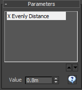
- To adjust the spacing of X Evenly rows you use the X Evenly parameter. This can be exported so that it can be accessed from the Parameters rollout. To do this, Right click on the generator and click Export > X Evenly > X Evenly Distance
- Wire a new Numeric node to the generator's X Evenly Distance input. Change the type to Scene Units.
- You can now change the spacing from the Parameters rollout in the Modify panel. For now we'll use a value of 0.8m.
![Parameterising Windows-image2015-11-20 18:2:42.png]()
In order for this to work X Evenly > Extend to Side must be turned on
Adding the transoms using Sequence operators
To add the transoms we'll use a different technique.
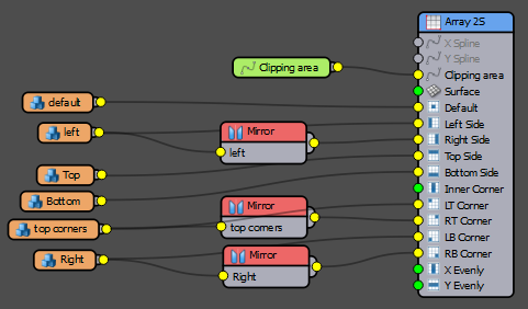
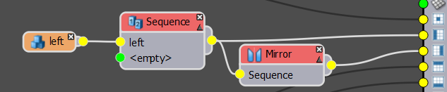
- Create a new Sequence operator and wire it between the Default segment and the Generator.
- Create another Sequence operator and wire it between the Left segment and the Generator, make sure it is also before the existing Mirror node.
![Parameterising Windows-image2015-11-20 18:6:55.png]()
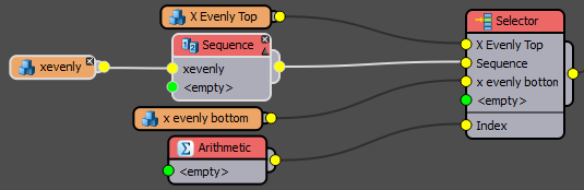
- Create a third new Sequence operator and wire it between the X Evenly segment and the existing Selector operator.
![Parameterising Windows-image2015-11-20 18:16:4.png]()
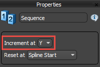
- Set all 3 Sequence operators to Increment at > Y
![Parameterising Windows-image2015-11-20 18:17:42.png]()
- Next we'll add the transom parts to the Sequence operator's second inputs. Duplicate a Segment node and pick the Y Evenly object from the scene. Wire this to the Sequence operator wired to the Default input.
- Duplicate a Segment node and pick the Y Evenly Left object from the scene. Wire this to the Sequence operator wired to the Left input.
- Duplicate a Segment node and pick the Evenly Junction object from the scene. Wire this to the Sequence operator wired to the X Evenly input. If necessary, swap the order of the inputs.
- Nearly there - we want to be able to control the size of the glazed section. We'll do this using the Fixed Size parameter of the Default, X Evenly and Left segment's. To ensure they are identical and easy to adjust without opening the style editor we'll export this value and attach a Numeric node.
- Right click on the Default segment and select Export Parameters > Fixed Size > Fixed Size > Y. Do the same for the X Evenly and Left segments.
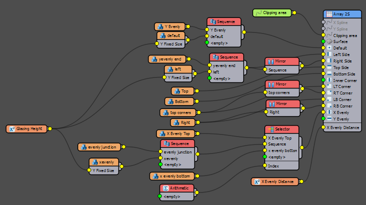
- Create a new Numeric node and set the type to Scene Units. Wire this to the Y Fixed Size inputs we just created. You can now control the height of the glazed portion of the window from the Parameters rollout. The finished node graph for the window object is shown below.
![Parameterising Windows-image2015-11-20 18:30:28.png]()
Creating multiple windows in one click
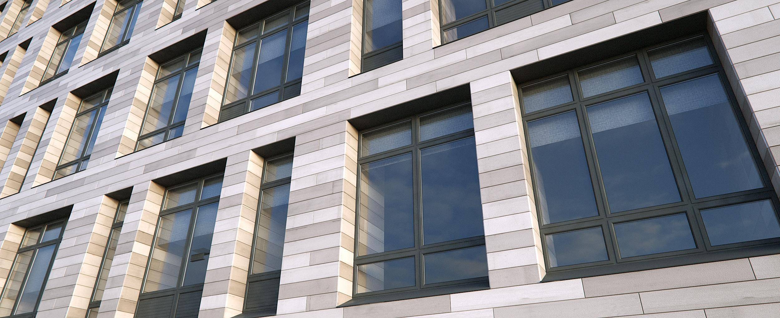
Here's were all that hard work pays off. In this scene there is a facade with 67 different sized windows. Also in the scene is a single spline object that consists of a rectangle for each window aperture.
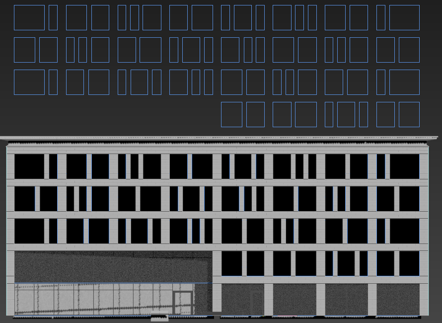
When you use a Extend X/Y Size to area and a Clipping object that consists of multiple splines RailClone will generate a new array for each spline. This means that in each rectangle we will get a separate unique window of the correct size. To illustrate this, let's add our window model to this façade.
- First rotate the RailClone object 90 degrees so that it is oriented with the z axis perpendicular to the façade. The Clipping spline is always projected along the Z axis in Extend X/Y Size to Area mode.
- Go to the Base Objects rollout and select Clipping Area. Assign the spline that can be found just inside the window openings.
- That's it! You'll just have created 67 unique windows. Because it's fully parametric you can easily change the size or adjust the X Evenly distance or glazing height.
Conclusion
Using these technique you should be able to parametrise many types of window and as mentioned at the beginning, the second one you create should be much simpler as you already have the style set-up and only need to swap the geometry. Some companies may find it beneficial to create a library of generic windows that can be used or adapted for their projects, if you're interested in creating custom libraries for RailClone, check out the last chapter of our Next Steps with RailClone guide. In our next tutorial instalment we'll extend the technique and look at how to create a roller blind style with a randomised openness setting to add some life-like variation to the windows. Meanwhile, stay tuned for future training, or for more information about many aspects of RailClone's features please see our reference section or visit the tutorials page for more Tips&Tricks videos and in-depth tutorials.