Файлы ресурсов
Требования
- info Forest Pack Pro
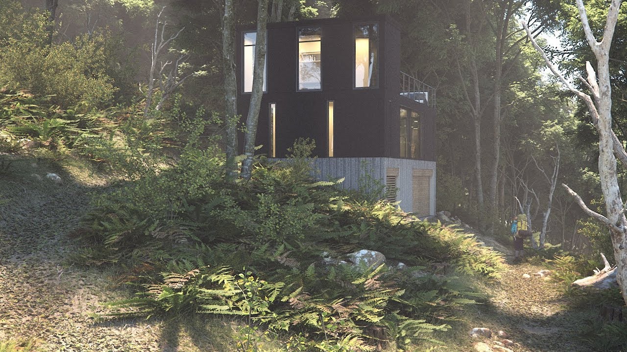

In this tutorial we look at how to use assets created using photo scanning techniques in conjunction with Forest Pack Pro including how to use surfaces, import and use photogrammetry models, and prepare 3D assets from texture atlases.
In the process we'll demonstrate a complete workflow for creating a woodland scene by layering 10 Forest Pack objects, and look at the key settings used to control each of the scatters.
Note on the Assets
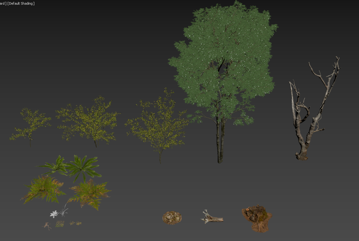
We'll be using Megascans and Evermotion content in this tutorial, although assets created yourself or from other suppliers will also work with these procedures. Even if you don't yet use these libraries, many of the principles will be useful for your scenes. The assets used are listed below.
- The tree used in this scene is a sample from Evermotion's AM163 collection of trees, all of which feature detailed photo scanned trunks. If you want to follow along with the tutorial you can download the model free from their website.
- For licensing reasons Megascans content is not supplied with the downloads for this tutorial, so if you want to follow along you'll either need a Megascans account, or you can substitute the materials we use for content from the free samples section of the Megascans library. The full list of assets used in this scene, including links, is shown below.
Scene setup and Surfaces
Megascans organise their assets into 4 categories: surfaces, atlases, 3D objects, and a new range of 3D plants. We'll take a look at each of these in turn as we build up a small woodland scene. Here's how the environment looks before we add scattered assets.
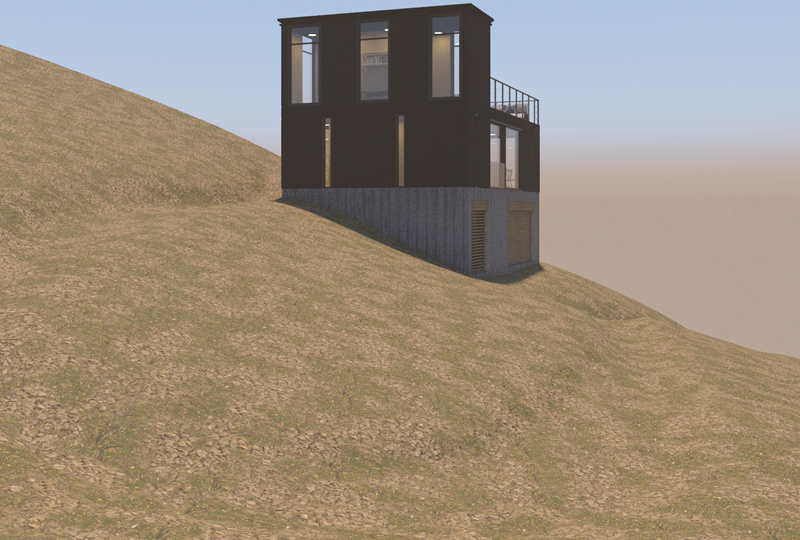
It's pretty basic, we only have a couple of terrains, one with a footpath, plus the building to work with. We're also going to need one more thing: a spline that follows the footpath that we will use to drive nearly all of the Forest Pack objects. You can easily extract one from the terrain geometry by selecting an edge from the middle of the path and clicking Loop to select a centre line. Click on Create shape from Selection and use the default settings to generate the spline.
As well as being invauable for Forest Pack, this spline also gives us the ability to apply a separate material to the footpath area by using a distance Map. This works by applying a texture based on the surfaces proximity to the spline we just created. In this tutorial we'll be using V-Ray, but Corona and other renderers also have this feature.
For a Distance map to work, the spline needs to be a mesh object, so select the spline, go to the Rendering rollout and turn on Enable in Viewport. Leave Enable in Render turned off, otherwise you'll see the spline in the final image. The thickness can be left quite small, because it's the distance from this spline that matters. 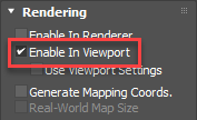
In the sample scene there's already a simple material applied to this surface that uses a couple of leaf materials mixed with noise, but now we'll add a third just for the path. (Most of the surface will be covered with scattered objects, so I'm not worried about the textures tiling.)
- First we'll examine the exising material. Open the material editor and pick the material from the terrain. There are a couple of surface materials already applied, mixed using a noise map in a V-Ray Blend Material. Let's add a third material from the Megascans collection.
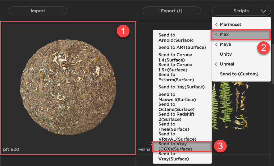
- To import a surface material to 3ds Max you can use Megascans Bridge. All you need to do is select the surface you wish to use, go to the Scripts dropdown and select Max, then Send to Vray(GGX) (or a different preset if you are using another renderer)
![Using Megascans products with Forest Pack-image2017-9-8_16-22-21.png]()
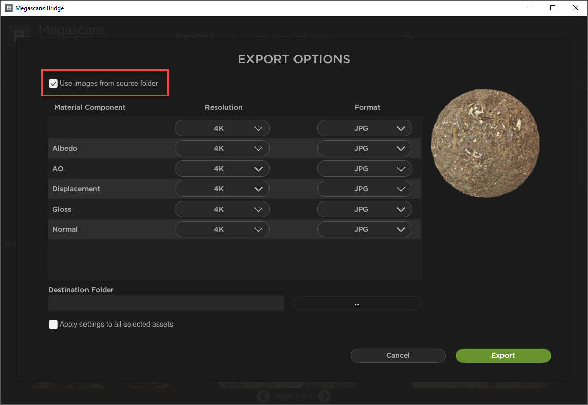
- From the Export Options choose the resolution and format, as well as whether to copy the images to another folder. Generally we turn on Use Images from Sourcefolder to leave them where they are.
![Using Megascans products with Forest Pack-image2017-9-8_16-26-32.png]()
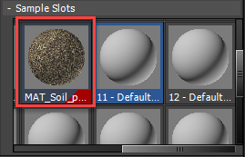
- Click Export. Return to Max, and you'll find that the material has been added to the next available sample slot, ready to use.
![Using Megascans products with Forest Pack-image2017-9-8_16-28-19.png]()
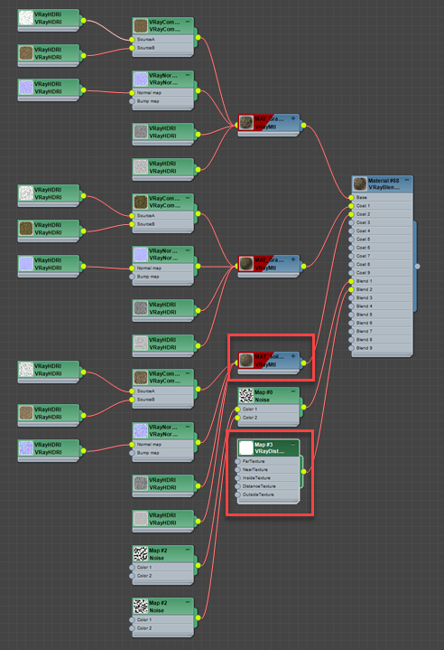
- You can now add this material to the existing V-Ray Blend material. Wiring it to a Coat input.
- Now we can add a mask to reveal this material on the footpath. Create a new V-Ray Distance Texture map and wire it to the appropriate Blend input.
![Using Megascans products with Forest Pack-image2017-9-8_17-17-2.png]()
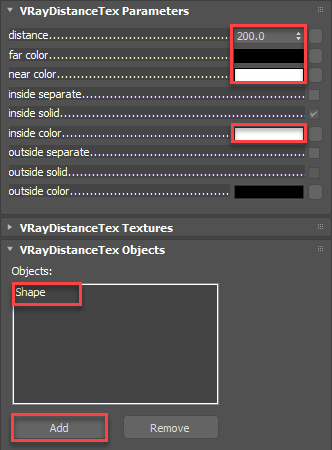
- In the V-Ray Distance Texture's settings, go to the Objects rollout, click on Add and pick the spline we just created from the scene.
- Change the Far colour to black, and the Near and Inside colour to white. This will create a black and white mask that reveals the material in the area close to the spline.
- Finally to control the how far either side of the spline this material should show, increase the Distance value. A setting of 200 works in this scene, but you'll need to experiment.
![Using Megascans products with Forest Pack-image2017-9-8_17-27-19.png]()
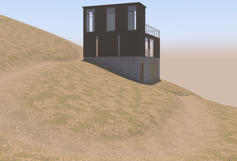
If you render now, you'll have see the new material only where the path is. Because this is determined by a spline, you can easily edit the path and the textures will automatically update too!
Adding the trees
With basic materials applied we're ready to start scattering objects, starting with the trees. There's actually only one tree model used in this scene, but of course you could use more for improved variety and realism. The one seen in the render is a free sample from Evermotion's AM163 collection of trees with photoscanned trunks. If you want to follow along with this tutorials you can download it from their website. To add the trees to the terrain:
- Create a new Forest Pack object by clicking on the terrain. Go to the Surfaces rollout and add the background terrain as well. This surface slopes away from the scene and just fills out the background to hide the horizon.
- Go to the Geometry rollout, select the existing scatter item and change the mode to Custom Object. Click on the object picker button and choose the tree model from the scene. If a warning appears about optimising Forest Pack for high resolution geometry, accept the suggestions.
- To randomise the tree, go to the Transform rollout and enable Translation, Rotation and Scale. Leave them at their default settings, except for scale which we'll change to a Min value of 150% and a Max of 300%. This will increase the size of the trees and add a lot of variation.
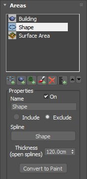
- The trees are currently on the path and intersecting the building. To remove them from these areas go to the Areas rollout and click Add Spline Area. Select the footpath spline that we created earlier and change the mode to Exclude. Increase the Thickness value to remove trees from the footpath and surrounding area.
![Using Megascans products with Forest Pack-image2017-9-8_17-48-29.png]()
- To remove trees from the building, click the Add Object Area button and pick the building from the scene. If you want to change the distance around the building that trees can be scattered, use the Scale parameter, to increase the accuracy of the collision detection, increase the Resolution. (Internally Forest Pack creates a black and white mask by projecting exclude objects on the world's Z Axis).
- To control the number and spacing of the trees, go to the Distribution Map rollout and change the Density to about 19,000 cm. You can also just judge this by eye. Feel free to use the X and Y Offset values to slide the Distribution map around on the surface to fine-tune the scatter.
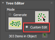
- Finally, if you want to perfect the layout of the trees you can enter Custom Edit mode from the Tree Editor rollout. This mode allows you to transform, add, and delete individual objects. When you activate it you'll get a couple of warnings, firstly that you're disabling distribution mode (essentially baking the trees in place), and secondly asking if you want to make visible the trees that are removed because they're outside the camera view. In this case the camera is fixed so we'll leave them hidden. We'll remove some trees from the mid ground that are obscuring the building by selecting and deleting them. You can also clone, rotate, and scale trees to get just the composition you're after.
![Using Megascans products with Forest Pack-image2017-9-11_9-24-26.png]()
Using 3D Objects with Forest Pack
One of the great advantages of photogrammetry is its ability to acquire highly realistic 3D assets. In this section we'll demonstrate how to import them using Megascans bridge and set up scatters using Forest Pack to add twigs, branches, trunks and fallen trees on and around the path. The import process for 3d objects is very similar to surfaces:
- Once you've downloaded your assets from the Megascans website, open Megascans Bridge.
- Select the model you wish to import.
- Go to the Scripts dropdown and select Max, then Send to Vray (GGX) (or a different preset if you are using another renderer).
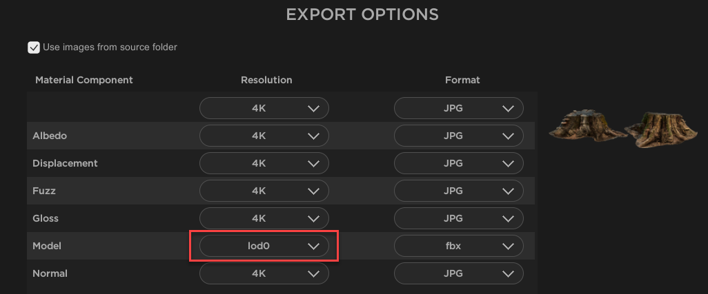
- From the Export Options you can choose the LOD, texture resolution and format, as well as whether to copy the images to another folder. We're going to use LOD0 to reduce memory usage, but if you have a powerful system, you can go for the high poly versions.
![Using Megascans products with Forest Pack-image2017-9-11_10-2-23.png]()
- Click Export and the file will automatically be imported into 3ds Max. Materials are created from the maps and automatically applied.
- Go through the same process for all the 3D models you wish to import. We're going to add a standing dead tree, a tree stump, a fallen tree, and some rocks.
Hero models like this would typically be manually-placed, but even so it's worth adding them to a Forest Pack object. In that way you'll benefit from impovements in memory management and render speed, as well as Forest Pack's transform and texture randomisation features should you want to use them. To use Forest Pack to manually position objects.
- Go to the Create panel and select Itoo Software from the drop-down list.
- Click on Forest Pack and change the mode to Custom Edit. In this mode you click in the scene to manually place an object. It will appear as a billboard as we've yet to add any geometry.
- Go to the Geometry rollout, select the existing item and change the mode to Custom Object. Pick one of the objects we just imported from Megascans Bridge.
- Repeat the process for all the other items. When you're done we're ready to start positioning the objects in the scene.
- Go to the Tree Editor rollout and click on the tree button
![Using Megascans products with Forest Pack-image2017-9-11_13-53-27.png]() to enter sub-object level.
to enter sub-object level. - Below this is the Add Items group. Click on Add and start clicking in the scene to add items. You can choose which item to place using the drop-down menu.
![Using Megascans products with Forest Pack-image2017-9-11_13-54-47.png]()
- Once an item is placed, you can use Max's standard Rotate, Transform and Scale tools to place them precisely where you need them. I added some rocks around the path, a couple of tree stumps in the foreground and some dead trees. You can also clone objects in this mode by holding down shift as you transform them. I won't show this entire process in the video because it's basically the same as positioning them manually.
 to enter sub-object level.
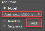
Adding fallen branches
The Megascans library includes many assets that are designed specifically for scattering. Here we're going to add some branches amidst the undergrowth and smaller twigs on the path.
- Importing Megascans scatter objects is really no different from importing hero objects, just select an asset in Megascans Bridge and use the export scripts to take care of the rest. The only difference is that you'll end up with several objects in Max, instead of just one.
- Create a new Forest Pack object using the terrain as a Surface. Change the Surface Normal slider to 0. in that way the objects will rotate to follow the geometry, reducing interpenetration with the terrain.
- Go to the Geometry rollout. Click on the
![Using Megascans products with Forest Pack-image2017-9-11_13-6-12.png]() button to add multiple objects. An object selector window will open, pick all the branch objects we just imported and click Add.
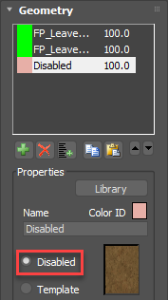
button to add multiple objects. An object selector window will open, pick all the branch objects we just imported and click Add. - Change the Colour ID of all the items to the same colour. We wil use this later in the Distribution settings.
![Using Megascans products with Forest Pack-image2017-9-18_18-49-17.png]()
- Add a new Item and set it to disabled. This will add spaces in the scatter and when used in conjunction with the Clusters feature, can add gaps in the scatter where there are no branches.
- Now let's randomise these objects, go to the Transform rollout and enable Translation, Rotation and Scale. Leave the Translation settings at their defaults. Zero the X rotation properties to stop the branches rotating through the surface. Change the scale to 40% Min and to 200% Max to introduce a much wider range of sizes.
- Enable Horizontal Mirroring to add further randomness to the objects.
- These branches are a bit of a trip hazard! To remove them from the path, go to the Areas rollout and add a new Shape area. Pick the footpath spline from the scene and set the mode to Exclude.
- Increase the Thickness property until the branches are cleared from the middle of the path. Ideally you'll want to be able to see them at the edges, but keep the majority of the path clear.
- In the Distribution rollout, change the Density to 950cm, or until you have the desired coverage of branches.
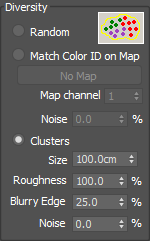
- At the moment the distribution is pretty uniform across the whole area. We'd like to add some patches where no branches appear, and to do this we use the Clusters feature. This allows you to group together plants that have the same Colour ID. Remember all the sticks have been assigned to one Colour ID, and a disabled item has a second, different, colour ID. What this means is that we can create gaps in the scatter by creating a cluster of disabled items. To do this enable Diversity > Clusters and change the size to approcimately 100cm.
![Using Megascans products with Forest Pack-image2017-9-18_18-49-47.png]()
- To change the ratio of the clusters use the Probability settings in the Geometry rollout. For example selecting all of the branch objects and reducing their probability will result in more gaps appearing in the scatter and a more convincing, broken up, distribution.
 button to add multiple objects. An object selector window will open, pick all the branch objects we just imported and click Add.
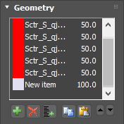
Adding twigs and debris to the path
With the large branches complete, we'll add some small twigs to the path. The procedure is more or less the same:
- Download and select a twigs asset in Megascans Bridge and use the built-in export scripts to transfer the models to Max.
- Create a new Forest Pack object using the terrain as a Surface. Change the Surface Normal slider to 0.
- Go to the Geometry rollout. Click on the
![Using Megascans products with Forest Pack-image2017-9-11_13-6-12.png]() button to add multiple objects. An object selector window will open, pick all the twig objects and click Add.
button to add multiple objects. An object selector window will open, pick all the twig objects and click Add. - Select all of the Items in the list and give them the same Colour ID. Set their Probability to 5%. This is to allow us to use the same clustering trick we demonstrated above.
- Add a new Item and set it to Disabled. Leave the probability on 100%. This will create more gaps in the clusters
- Go to the Areas rollout. Currently we're scattering on the whole surface, but realistically we'll only ever see this debris on the path. To achieve this, turn off the existing Surface and add a new Shape area. Pick the footpath spline from the scene and increase the thickness until the twigs overlap the side of the path. About 205cm worked well in this example.
![Using Megascans products with Forest Pack-image2017-9-18_18-51-17.png]()
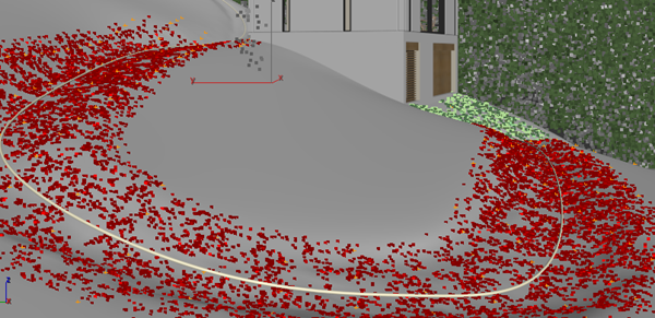
- Rather than stop apruptly as the twigs disapear into the undergrowth, it would be better if their density gradually decreased. To do that, enable Falloff > Density and increase the Include value to about 70cm. By default this feature uses a linear falloff graph to adjust the density based on the scattered items distance from the perimeter of an area. As we'll see later, these graphs can also be edited to create more sophisticated effects.
![Using Megascans products with Forest Pack-image2017-9-11_14-32-53.png]()
- Now let's change the global density. Go to the Distribution Map rollout and change the map to Groups 1. This will give us little clumps of twigs instead of the usual even distribution. Decrease the Density to 100cm to add more twigs and turn on Clusters. Reduce the size of the clusters to 50cm. You can also change the shape of the clusters using the Roughness setting, increase this to make them more angular.
Optimisation
When scattering thousands of small objects, it's a good idea to optimise the scene by reducing the number of scattered items based on their distance from the camera. Often these smaller objects are not visible in the background anyway. so it makes no sense to waste resources on them. Forest Pack has several techniques for culling geometry based on the camera view, and the following techniques can be used for most of the ground cover scatters in this scene.
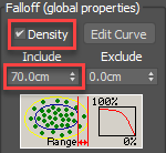
- Go to the Camera Rollout. Click on the Camera Picker and select a camera from the scene. By default this will remove any objects that are not visible in the render. If you need to, you can adjust the Far Clipping Plane, expand the camera Frustum slightly, as well as add offset in case you would like objects to render slightly behind the camera. This can be useful for ensuring that scattered items appear in reflections and cast shadows.
![Using Megascans products with Forest Pack-image2017-9-12_12-8-13.png]()
- Far Clipping Plane stops the scatter abruptly, but we can reduce the visibility of this if we gradually thin it out. To do this use the Distance Falloff settings. Turn on Density, set a Minimum and a Maximum value and the number of scattered items will dissolve to nothing over this distance.
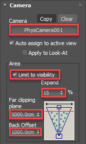
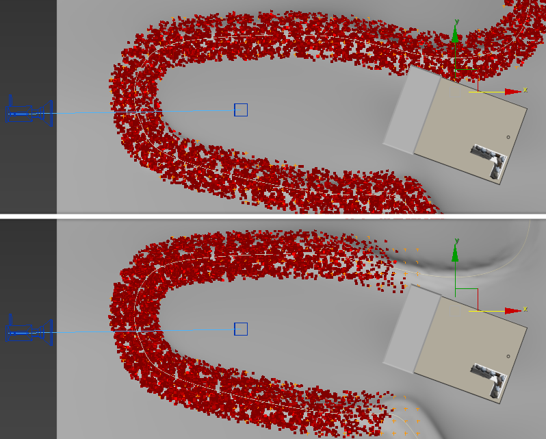
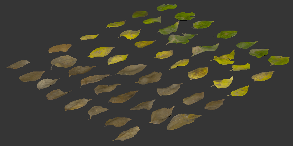
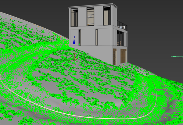
Below is a preview of the original distribution of the twigs, and the distribution after optimising.
Creating scatterable assets from atlases
The Megascans library also includes atlases. These are cutout textures with an opacity map, fantastic for creating leaves and modelling plants. They don't include a 3d model so we need to do a bit of work before we can use them with Forest Pack. There are already a few tutorials published about this process that either hand trace the atlasses with splines, or use ZBrush. We'll demonstrate a slightly different approach that uses an application called SpriteUV. This is an easy-to-use free or inexpensive tool that was originally designed for packing sprites, uvs and textures, but it's also ideal for automatically generating meshes that match the shapes contained in an atlas. To Illustrate how it works we'll take this leaf material and create 3d models that are ready to be used with Forest Pack and GrowFX.
- In Megascans Bridge select an atlas texture and export it to 3ds Max using a built-in script in the usual way.
- At the end of this export process, as well as placing the material in 3ds Max's material editor, explorer opens the folder containing all the maps. This is handy because we need to generate a map with an alpha channel for SpriteUV to work, and the easiest way to do this is to open the opacity map in Photoshop (or you're chosen image editing software) and cut out the background so you're left with only the leaves.
- Before saving, reduce the resolution of the texture to 1024 x 1024. This size is a limitation of the free version of SpriteUV, but of course if you buy the full license of SpriteUV any size is OK, just be aware that larger resolutions will slightly increase processing time.
- Save the new map as a PNG, PSD, TIFF or another format that supports transparency.
- Open SpriteUV and import the map either by dragging it to the window or clicking to open the file browser.
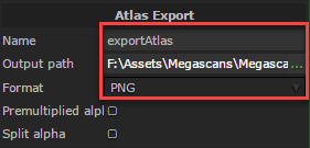
- First of all you'll need to set a couple of save paths in SpriteUV. On the left hand side select the Atlas List > Export Atlas option. We're not actually going to be exporting a texture, but you still need to set a path in order to build the mesh. In Output Path, select a location to save your files.
![Using Megascans products with Forest Pack-image2017-9-11_22-8-14.png]()
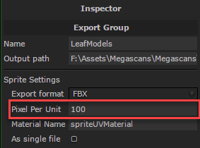
- Next go to the Mesh Export Group > Mesh Export options,set a path and assign a filename. The other important setting here is the Pixel Per Unit value. This is how the size of the resultant mesh is determined. The size of the mesh will be the resolution of the texture divided by this value. For example, if my scene units are set to CM, my opacity map is 1024 x 1024, and the Pixel Per Unit is set to 100 (the default), therefore the size of the model when imported into max will be 1024/100, or 10.24cm. We'll use this measurement to set the size of the UVW map as we'll see later.
![Using Megascans products with Forest Pack-image2017-9-11_22-9-26.png]()
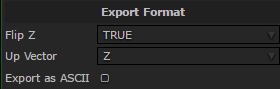
- Now we can configure the mesh - go to Mesh Format > FBX and change the Up Vector to Z and the turn on Flip Z.
![Using Megascans products with Forest Pack-image2017-9-11_22-9-46.png]()
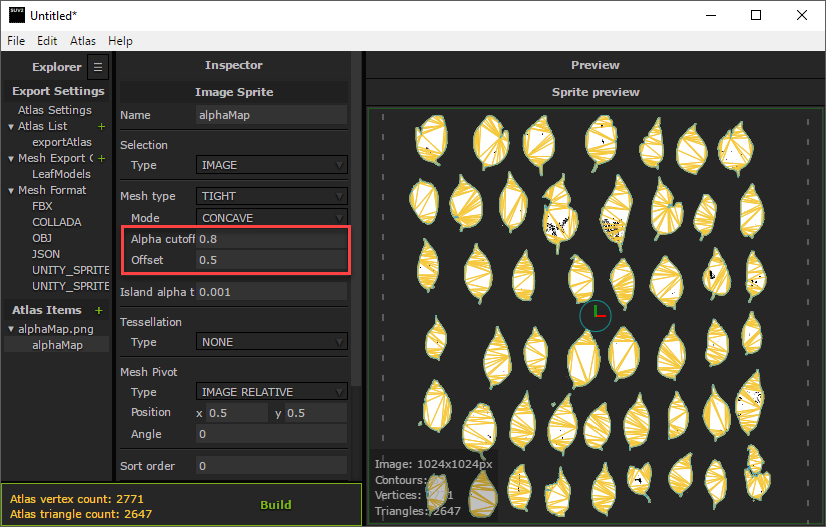
- Go to the Atlas Items settings. You'll see a preview of the mesh output. There are only a couple of paramters here we need to worry about. Offset, which adds padding around each leaf, and Alpha Cutoff which is a threshold used to detect the edge of each leaf. We try to get our mesh as close as possible to the texture to reduce the amount of transparency in the final render. This can really slow them down in some cirumstances. To get the mesh tighter, reduce the Offset value and increase the Alpha Cutoff.
![Using Megascans products with Forest Pack-image2017-9-11_22-10-51.png]()
- When you're happy with the results, turn on Export Mesh Only and click Build. A new FBX file will be created in your save location containing a mesh for each leaf.
That's it for the SpriteUV section. All that remains is to import the FBX into 3ds Max, adjust the UVs, apply materials and make a few other small changes.
- Import the FBX file into 3ds Max. For some reason when viewed from above the object is upside down, so immediately rotate it around the Z axis by 180 degrees and then reset the XForm.
- Apply the material imported from Megascans Bridge. If you show the diffuse texture in the viewports, you'll notice that the UVWs haven't been calculated, so we need to add them ourselves. Fortunately this is very easy.
- Apply a UVW modifier to the leaves. Set the size to 10.24cm x 10.24cm. You'll remember from earlier that this size was calculated by dividing the resolution of the original map by Pixel Per Unit value specified in SpriteUV.
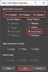
- Go to the Gizmo sub object level and use the Align tool to alight the gizmo to the leaf object's pivot. Your textures are now perfectly aligned to the mesh.
![Using Megascans products with Forest Pack-image2017-9-11_22-6-59.png]()
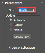
- We need to increase the resolution of the mesh so that it can be deformed. Add a Subdivide modifier and decrease the Size to get the required resolution.
![Using Megascans products with Forest Pack-image2017-9-11_22-6-10.png]()
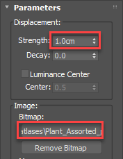
- Now we want to add some deformation to the leaves so that they're not flat. We could use a Bend modifer or add some Noise, but why not use the Displacement map that comes with the material? Apply a Displace modifier and make sure you turn on Use Existing Mapping.
- Copy the displacement map to the modifier's Bitmap input. Increase the Strength until you're happy with the amount of displacement.
![Using Megascans products with Forest Pack-image2017-9-11_21-49-57.png]()
- Add a Smooth modifier and turn on AutoSmooth. Our leaves are done and you can collapse the stack. All that remains is to detach them into separate objects and align the pivots.
- You can detach leaves manually by selecting each element and using the Edit Poly object's Detach option, or you can use one of the many scripts that are available to automate the process. We have RappaTools installed and we use the Explode Object option to speed up this process.
- The leaves are now separate objects, but you'll need to align the pivot for each one. Once again you can do this manually, by going to the Hierachy rollout, activating Affect Pivot Only and moving the pivot manually; or you can use a script. We're using Rappatools again to align the pivot to the center and then the bottom of the leaves.
- Select the leaves you wish to keep and delete any extras or other bits of the original atlas you don't want to scatter.
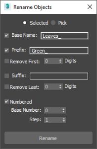
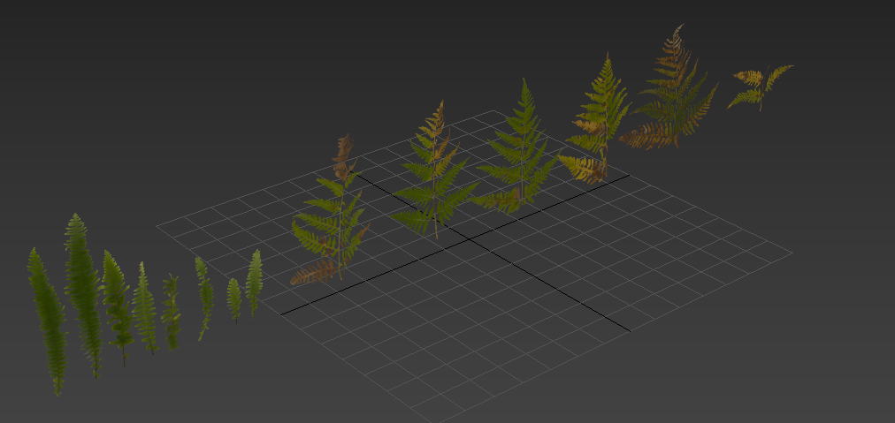
- To make it easier to identify the leaves in Forest Pack you should rename them. Launch Max's built-in Rename Objects tool found in the Tools menu. Select all the green leaves and enter the colour of the leaves in the rename tool's Prefix field. Enter Leaves in the Base Name field and turn on Numbered. Click Rename to update the names of the selected objects. Do the same thing for the yellow leaves and then the brown ones.
![Using Megascans products with Forest Pack-image2017-9-11_22-5-30.png]()
- Finally, uniformly Scale the leaves until they are the correct size, Reset the XForm and then collapse them to an Editable Polygon object. They're now ready to scatter!
![Using Megascans products with Forest Pack-image2017-9-11_22-11-59.png]()
Applying the leaves to the pathway
- To apply these leaves to our path, create a new Forest Pack object by selecting the Terrain.
- In the Surfaces rollout set the Direction to 0.
- To add the leaves go to the Geometry rollout, click on Add Multiple
![Using Megascans products with Forest Pack-image2017-9-11_23-18-42.png]() and select all the leaf assets.
and select all the leaf assets. - Change the Colour ID of all the leaves so that they are identical. We will employ the same clustering trick to add gaps in the distribution we used in the twigs scatter earlier in the tutorial.
- Now we need to get the mix of leaves right. Since these leaves are dead they should be mainly brown, with occasional greens and yellows. To achieve this, select all of the brown leaves and set the probability to 50%. Select the yellow leaves and set the probability to 2.5%. Finally select the green leaves and set the probability really low, about 0.5%
- To create gaps in the scatter add a new item and set it to Disabled. Make sure it has a different Colour ID to the leaves so that the Cluster feature works correctly.
- Add some randomisation by going to the Transform rollout and enabling Translation, Rotation and Scale.
- Set the Scale's Minimum to -200% and Maximum to 200% for the X and Y axis to break up the distribution pattern a bit.
- Set the Rotation's Minimum value to -20% and Maximum to 20% for the X and Y axis.
- Increase the range between the Scale's Minimum and Maximum for more variety in leaf size.
- At the moment we're scattering on the entire terrain, but we only want individual leaves on the path (we'll fill in the terrain with larger patches in the next section). To confine the scatter to this area, go to the Areas rollout and turn off the Surface area.
- Add a new Shape area and pick the footpath spline. Increase the size until the leaves cover the width of the path and up the sides, about 1.8m works well.
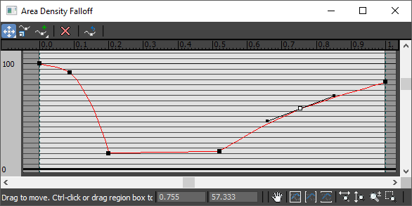
- There is a dip in the middle of the path where you'd expect more leaves to accumulate. To create this effect you can use custom falloff curves. Enable Density falloff and click the Edit Curve button and a graph opens. The X axis represents the distance from the edge, with the edge being on the right of the graph. The Y axis represents Density. To create a more leaves in the center and at the edge you should create a graph which has a dip in the middle, like this:
![Using Megascans products with Forest Pack-image2017-9-11_23-29-49.png]()
- Now you can change the Include distance to set the range over which this graph is calculated. I used about 140cm, but you can adjust it visually.
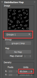
- The Distribution settings are very similar to the ones we used for the twigs. Choose the Groups 1 map and increase the number of leaves by reducing the Density setting.
![Using Megascans products with Forest Pack-image2017-9-12_11-28-47.png]()
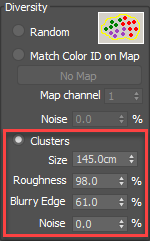
- Turn on Diversity > Clusters and set the size to about 150cm to create some decent sized gaps in the scatter.
- Make the clusters more ragged by increasing the Roughness value, and blend the boundaries between clusters by increasing Blurry Edge.
![Using Megascans products with Forest Pack-image2017-9-12_11-23-27.png]()
You'll now have leaves that follow the path, with a greater density in the center of the path and at the edge, broken up with occasional gaps.
Creating patches of leaves
To fill large areas normally we make patches of leaves. In a previous tutorial we've shown how you can make those patches with Forest Pack, but for objects like this that ideally should overlap and lay on top of one another it's hard to get a convincing stacking effect. Instead we like to use MassFX to create a more believable pile of leaves that can then be scattered with Forest Pack to fill large areas. Here's how:
- Create a Forest Pack object to scatter the leaves using the same technique as the previous example. Remember to change your probability settings to get the correct mix of colours and ages. In this example I'll assume this has already been done.
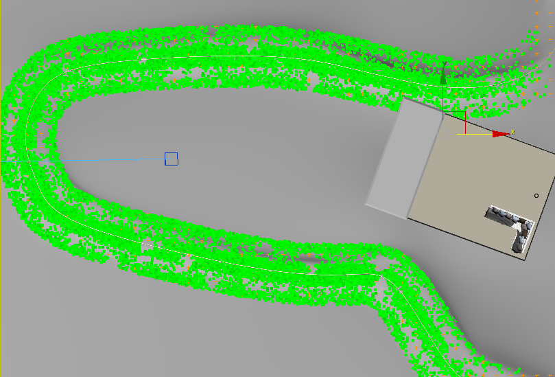
- Apply the Forest object to a small circle, about 15 cm works well.
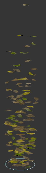
- Go to the Tranform rollout and enable Transform, Rotation, and Scale. Use the default settings except for Z Translate, Increase this significantly until the leaves are well spread out. Adjust the Density too if necessary
![Using Megascans products with Forest Pack-image2017-9-11_22-39-47.png]()
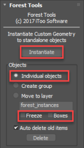
- Next we need to convert the Forest Object to native Max instances. To do this, go to the Utilities Panel, Click on More and load Forest Tools. Change the mode to Individual Objects and uncheck Freeze and Boxes. Click Instantiate and the leaves will be created in the scene as individual items.
![Using Megascans products with Forest Pack-image2017-9-11_22-46-20.png]()
- Next we'll use PhysX or MassFX, depending on which you have installed, to drop these leaves into a pile. To do this make sure you have the PhysX or MassFX toolbar visible, select all of the original leaf source objects and click Set Selected as Dynamic Rigid Body
![Using Megascans products with Forest Pack-image2017-9-11_22-48-15.png]() .
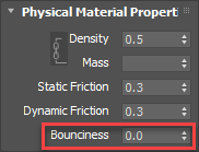
. - Open MassFX Tools and go to the Multi Object Editor tab. From here we can adjust the properties of the leaves. Change the Physical Materials >Bounciness value to 0 to minimise the amount the leaves will spring out of the stack when they land.
![Using Megascans products with Forest Pack-image2017-9-11_22-51-21.png]()
- Go to Simulation Tools and press the Start Simulation Without Animation button
![Using Megascans products with Forest Pack-image2017-9-11_22-52-0.png]() . The leaves will drop into a pile.
. The leaves will drop into a pile. - Click Capture Transform to lock in the new position. Select a single leaf and attach all the others until they are a single object. You can use a script if you have one, I'm using Rappatools again in this example.
- Reset the Xform and edit the pivot and you now have a new patch, ready to be scattered with Forest Pack. You can run this process a few times to get different variations and help disguise repetition in your scatters.
 .
.
 . The leaves will drop into a pile.
 Filling large areas with leaves
Now we have a couple of large patches we can scatter them across the rest of the terrain.
- Create a new Forest Pack object using the terrain. In the surfaces rollout make sure you set the Direction to 0, otherwise the edges of the patches become very obvious on sloped terrains.
- Go to the Geometry rollout and add the leaf patches. Give them the same Colour ID so that we can use the clustering feature.
- Add a new item and set it to Disabled,
![Using Megascans products with Forest Pack-image2017-9-12_11-49-43.png]()
- Add randomisation by going to the Transform rollout and turning on Translation, Rotation and Scale. The default settings are find for this kind of distribution.
- We already have leaves on the path, so we need to exclude these patches from that part of the terrain. Do this by going to the Areas rollout. Add a new Shape area, set the mode to Exclude and increase the Thickness value until the patches are removed from the path. They should roughly connect to the existing leaves.
- Now change the number of patches by opening the Distribution rollout and adjustting the Density value.
- Finally Turn on Diversity > Clusters and adjust the Size to add some random gaps to the distribution.
![Using Megascans products with Forest Pack-image2017-9-12_11-58-12.png]()
Scattering the Ferns and Saplings
The leaves for the ferns and in the saplings in this scene were created from Megascans atlases prepared in exactly the same way as the previous example. This time they were used in conjunction with GrowFX to create plants. There isn't time in this tutorial to go through the full GrowFX process, and there are several helpful tutorials on Exlevel's website that can help with this if you want to learn more, but here's a couple of the most salient points.
- For GrowFX the leaves should be aligned so that they point up, along the Z axis. Their flat side should point along the Y axis.
![Using Megascans products with Forest Pack-image2017-9-12_13-26-32.png]()
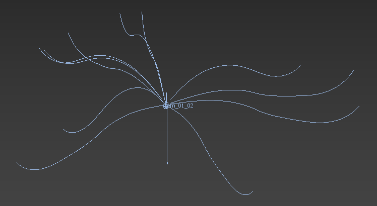
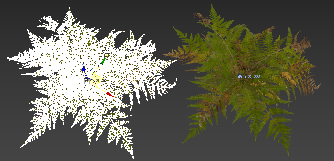
- GrowFX Object were prepared in the usual way, with paths to define the placement and deformation of the leaves
![Using Megascans products with Forest Pack-image2017-9-12_13-27-26.png]()
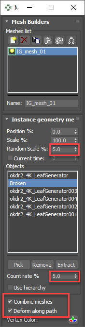
- In GrowFX, use the Instanced Mesh builder to add the atlas geometry to the plant. Just like Forest Pack, you have options to control the probability of items, randomise the scale and more. If you want to deform the leaves to follow the splines, make sure that you enable Combine Meshes and Deform Along Path.
![Using Megascans products with Forest Pack-image2017-9-12_13-29-13.png]()
In case you don't have GrowFX, We've included meshes for the saplings and the ferns in the scene file. All you need to do is import the same atlases that we used from Megascans Bridge, and apply them to the models.
We'll look at scattering the saplings first. It's pretty straightforward, we just need to make sure they don't grow through the existing trees, building and the footpath.
- Create a new Forest Pack object by picking the Terrain.
- Go to the Geometry rollout and add the Sapling models.
- Add randomisation by going to the Transform rollout and turning on Translation, Rotation and Scale. Once again, the default settings are fine, but we reduced the Minimum scale a bit to create smaller trees.
- To remove the saplings from the path, go to the Areas rollout and add a new Shape Area. Pick the path spline from scene, set the mode to Exclude and increase the Thickness until the trees are removed from the footpath.
- Remove the saplings from the building by adding a new Object area and picking the house from the scene.
- We also want to remove saplings from around the existing trees. Add a new Forest Area by clicking the
![Using Megascans products with Forest Pack-image2017-9-12_13-42-37.png]() button and then picking the trees Forest object from the scene. The collision detection takes into consideration the tree's canopy, but we're really only interested in the trunk. To compensate for this, reduce the Scale value.
button and then picking the trees Forest object from the scene. The collision detection takes into consideration the tree's canopy, but we're really only interested in the trunk. To compensate for this, reduce the Scale value. ![Using Megascans products with Forest Pack-image2017-9-12_13-44-15.png]()
- Add a second Forest Area and select the Forest Pack used for the hero models to ensure they are not covered by the saplings. Again you may need to reduce the scale a little.
- Finally, go to the Distribution rollout and adjust the Density settings until you're happy with the amount of saplings.
 button and then picking the trees Forest object from the scene. The collision detection takes into consideration the tree's canopy, but we're really only interested in the trunk. To compensate for this, reduce the Scale value.
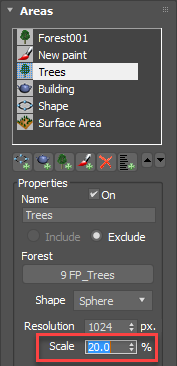
More or less the same principle also applies to the ferns. In our scene there are two types of ferns that we'll create in separate clusters alongside some gaps.
- Create a new Forest Pack object by picking the Terrain.
- Go to the Geometry rollout and add the fern models. Give the two types of ferns separate colour IDs so that they'll appear in different clusters. Add also a disabled item and reduce the probability to 35%.
- Add randomisation by going to the Transform rollout and turning on Rotation and Scale. Change the Minimum scale to 40% and the maximum to 180% for more variety in the sizes.
- To remove the ferns from the path, go to the Areas rollout and add a new Shape Area. Set the mode to Exclude and increase the Thickness until the trees are removed from the footpath.
- Add a new Object area and picking the house from the scene.
- Add new Forest areas for the trees and the hero models as we did in the previous example.
- Lastly, go to the distribution rollout and adjust the Density and Clusters settings.
Plants
To finish this tutorial we'll look at the final category of objects in the Megascans library, 3D plants created from scan data. There are both individual plants and small patches suitable for covering large areas. In this last step we'll add some small grass and weed models to the edges of the path to ease the transition between the dried leaves and the undergrowth.
- Using Megascans Bridge, import the plants you wish to scatter. The process is exactly the same as for importing the 3D models.
- In 3ds Max, make sure the plants are aligned correctly, occasionally I find I need to rotate them and reset the XForm.
- Create a new Forest Pack object, by clicking on the terrain.
- Add the plants to the Items List and adjust probabilities as appropriate.
- Add randomisation by going to the Transform rollout and turning on Rotation and Scale. The grass is a bit too long so change the Minimum scale to 50% and the maximum to 80%.
- In the Areas rollout disable the surface and add a new Shape area. Pick the footpath spline and increase the thickness so the the grass extends into the undergrowth.
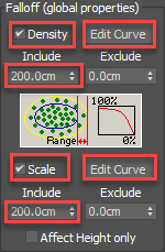
- Turn on Density Falloff and increase the Include value to the same Thickness as the path.
![Using Megascans products with Forest Pack-image2017-9-12_14-35-35.png]()
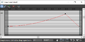
- We want to remove grass from the center of the path, to do this, edit the falloff curve and create a graph that spikes on the right hand side, as shown below.
![Using Megascans products with Forest Pack-image2017-9-12_14-33-49.png]()
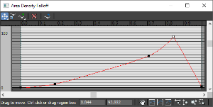
- We also want the grass to decrease in size as it gets closer to the center of the path. To do this enable Scale Falloff, use a similar value for the Include setting and edit the curve to use the shape shown below.
![Using Megascans products with Forest Pack-image2017-9-12_14-37-13.png]()
- Open the DistributionMap rollout and adjust the Density to get a good packed distribution of plants. Our scene is now complete and ready to render!
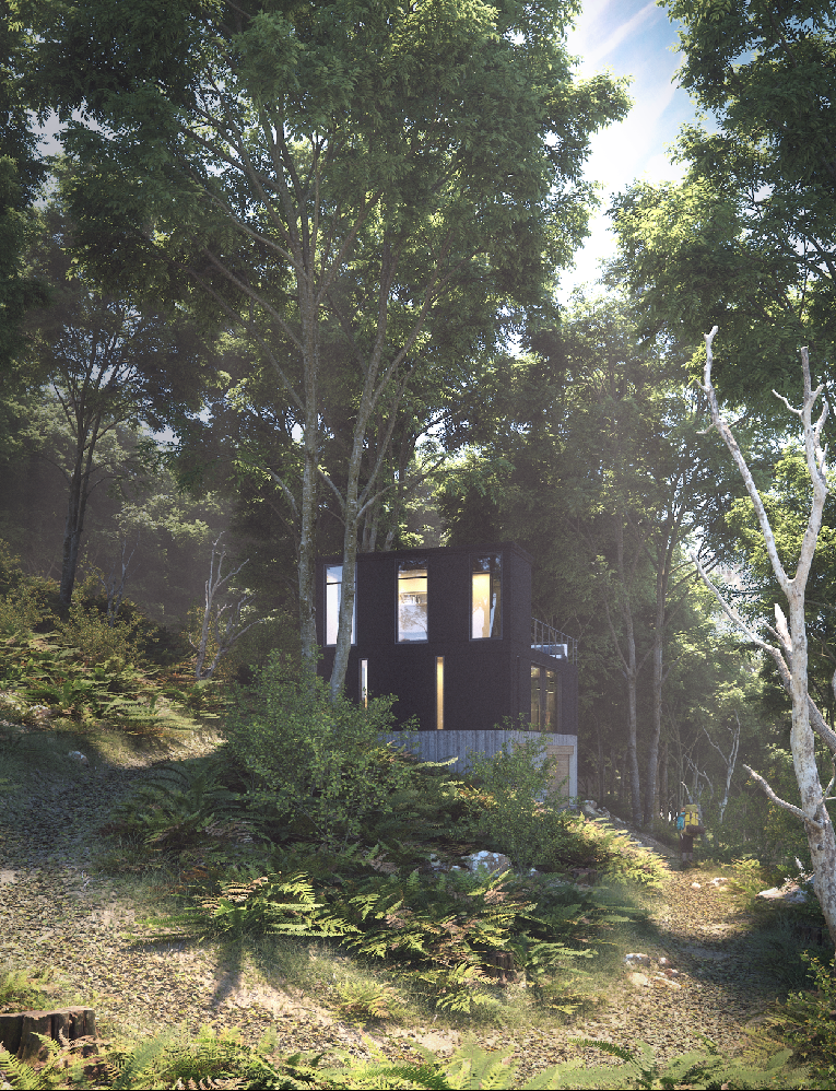
Conclusion
This concludes the tutorial. We've layered up 10 Forest Pack objects onto a single surface, each affected by the same spline so that if you wanted to adjust the path, you'd only need to edit one object. Enabling each scatter in turn we can see how they interact.
We have one Forest Pack object each for the twigs, the leaves on the path, the fallen branches, the patches of leaves, the grass on the side of the path, the hero models, the saplings, the ferns, and finally the trees. Although here we looked at a particular scene the principles should be easy to adapt to any other combination of splines and surfaces as well as other types of assets. If you use these tutorial files, or the techniques shown in this tutoral, to create any variations on this scene we'd love to see them on our forum. Otherwise, stay tuned for our next tips and tricks installment and check out our other videos in the tutorials section of the website.