Resources
Requirements
- info 3DS Max 2011, RailClone Pro, RailClone Lite
Introduction
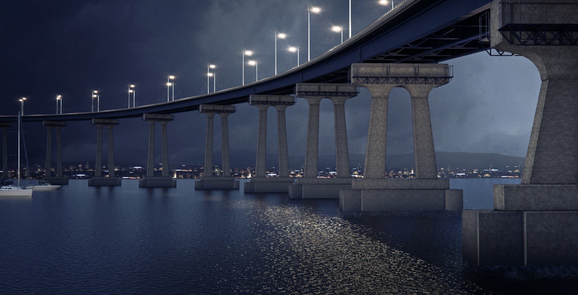
Many types of Bridge are easy to create with RailClone's linear generator. In this Tips and Tricks episode we look at two ways to create a bridge with a typical beam construction. In the first part of this tutorial we'll build a fixed-height style that's compatible with RailClone Lite. In the second part we'll use RailClone Pro to create a bridge with a deck that is able to deform on the Z axis with piers that automatically scale to support it.
By completing this tutorial you will be able to:
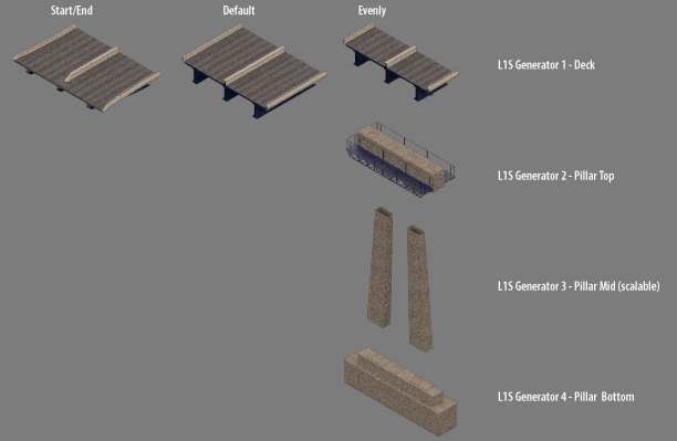
- Use the start, end, default and evenly inputs of an L1S generator in RailClone Lite.
- Create an expression in the Arithmetic operator using XSplineCoords to extract the Z height of the spline at a given segment position.
- Create a 3 part bridge pillar that automatically scales between the Z coordinate of the RailClone object and the Z position on the X Spline to allow for a deck with a varying height.
- Use automatic box mapping.
Download Contents
The exercise files for this tutorial includes the following .max scenes compatible with V-Ray and Max 2010.
- bridge_start.max The starting file if you want to follow the tutorial.
- bridge_end.max The result of the completed tutorial
Creating the style.
Part 1 - Fixed Height Bridge (RailClone Lite)
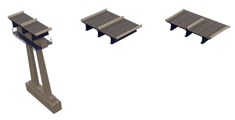
RailClone Lite can use up to 3 segments with a single L1S generator. To maintain compatibility this bridge style has been split up into a start and end segment, a default segment that forms the majority of the deck of the bridge, and a combined pillar and joint segment.
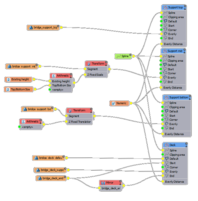
Below is the node tree for this style.
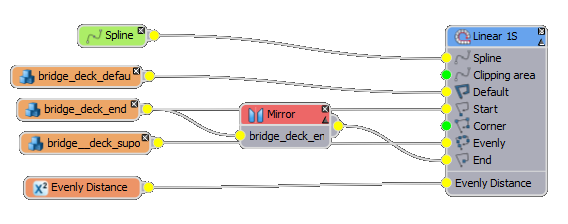
To create this style, follow these steps:
- Open bridge_start.max from the downloads that come with this tutorial.
- Create a new RailClone object.
- Open the Style Editor and drag a new L1S generator from the Items Panel to the Construction View.
- Create a new Spline object and pick spline_fixed_height from the scene.
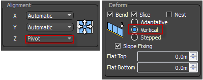
- Create a new Segment object. Set Properties>General>Alignment>Z to Pivot and Properties>Deform mode to Vertical. This will ensure the supports remain upright.
![Building Bridges-beg1.png]()
- Click on the Properties>General>Object button and select the mesh called bridge_deck_default.
- Connect the Segment node into the Default input of the L1S generator.
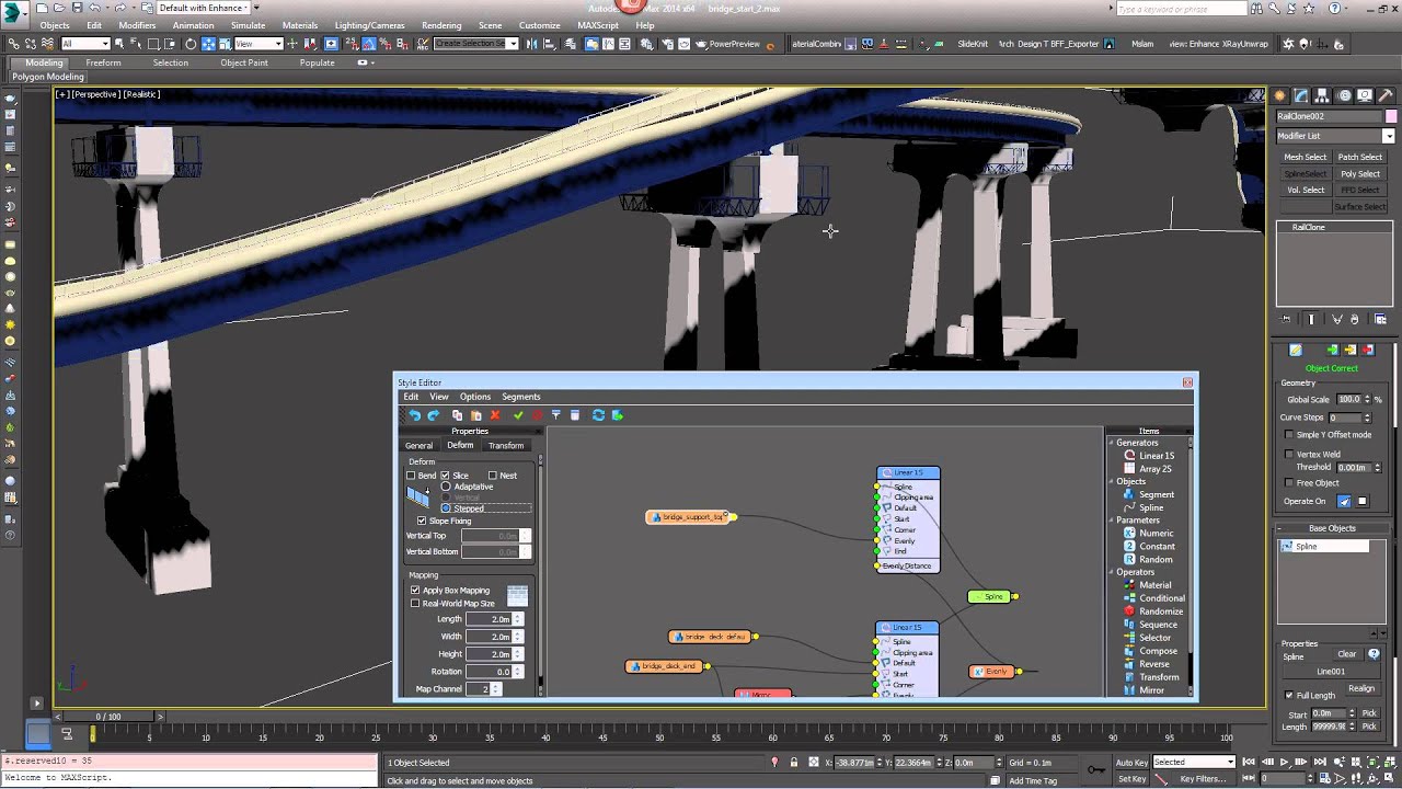
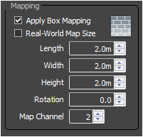
- To prevent the road surface texture from revealing seams where adjacent segments connect, it is possible to add box mapping that follows the spline using RailClone. To do this go to the segment's Properties>Deform>Mapping and turn On Apply Box Mapping. Enter a value of 2m for the Length, Width and Height. The bitmap used on the road surface is set to use a UV channel of 2 so to target only that bitmap, change the Properties>Deform>Mapping>Map Channel value to 2.
![Building Bridges-beg2.png]()
- To retain these setting for the other segments, we can copy and paste this node. With the Segment selected press Ctrl+C then Ctrl+V to copy and paste.
- With the new node selected press the Properties>General>Object button and select the mesh named bridge_deck_end then connect it to the Start input.
- Wire the bridge_deck_end segment to a new Mirror operator, then wire the Mirror operator to the End input of the generator.
- Add the supports by copying and pasting either segment a third time, this time pick bridge_deck_support_fixed from the scene and connect to the Evenly input.
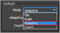
- Select the L1S generator and change Properties>Deform>Default mode to Adaptive to prevent a segment being sliced.
![Building Bridges-beg3.png]()
- To enable easy access to the pier's spacing export the Evenly value by right clicking on the generator and going to Export>Evenly Distance. Create a new Numerical node, set the Type to Scene Units and wire to the newly exported property. You can now adjust the bridge supports spacing from the Parameters rollout in the modify panel.
Part 2 - Variable Height Bridge (RailClone Pro)
The bridge created in the previous section is fine if you don't need to vary the height of the deck along it's path, by using RailClone Pro though we can create a more advanced style with enables an undulating deck with concrete piers that automatically scale to meet the spline. To make it more interesting the pier geometry has been split into three sections: With a top and bottom that retain a fixed height, and a mid section that scales to fill the difference.
To create this style follow these steps:
- Clone the RailClone object created in Part 1 and assign spline_variable_height.
- We'll keep the existing L1S generator but in this example it will only be used to create the bridge deck. The supports will be created using three further generators - one each for the top, middle and bottom as demonstrated below..
Before creating these, select the evenly segment and swap the Properties>General>Object for bridge_deck_support.
![Building Bridges-nodeAdvanced.png]()
- To create the top of the support piers copy and paste the existing L1S generator to retain its existing settings, splines and exported properties. Rename the new generator Support Top.
- Create a new segment and pick bridge_support_top from the scene. Connect to the Evenly input.
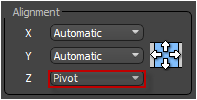
- The geometry for this segment already has a pivot point aligned to the top of the road surface. To use this change Properties>General>Alignment>Z from Automatic to Pivot.
![Building Bridges-int1.png]()
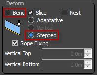
- To stop the geometry from bending along the spline, turn Off Properties>Deform>Bend and set the mode to Stepped.
![Building Bridges-int2.png]()
- Clone this generator including the evenly segment and rename it to Support Bottom. For the new segment pick bridge_support_bottom from the scene and set Properties>General>Alignment>Z to Automatic.
- Wire a new Transform operator between this segment and the Evenly input and export Z Fixed Translation.
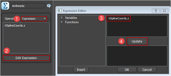
- We need to move this segment down so that it always sits exactly on the RailClone object's Z position instead of following the spline. To do this it's necessary to determine the Z distance between the RailClone object and the spline at the segment's current position. Luckily there's a function in the Arithmetic operator that does just that. Create a new Arithmetic operator and set the Operation Type to Expression. Click Edit Expression and enter -XSplineCoords.z. Note that the variable has been made negative to move the segment down on the Z axis, below the spline. Wire the Arithmetic node's output to the new transform operators exported Z Fixed Translation input.
![Building Bridges-int3.png]()
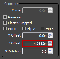
- We have now created the top and bottom of the piers. To create the mid section, select and clone the Support Bottom generator including the segment, transform and arithmetic nodes. Select the new generator and change Properties>General>Z Offset to -4.3682m.
For the new segment swap the geometry to bridge_support_mid. Select the new Transform operator and export Z Fixed Scale, swap the arithmetic operator so that it is attached to this new input slot.
![Building Bridges-int4.png]()
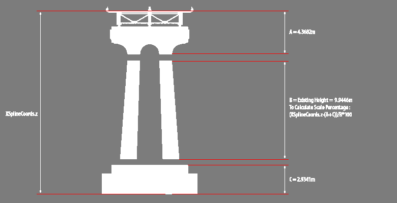
- As we've just seen we can use XSplineCoords.z to find the distance between the RailClone objects pivot point and the z position at the segments location along the spline. By deducting the heights of the top and bottom sections from this value we can find the measurement required for the middle section to fill the remaining space. Unfortunately segment's do not currently have a Z height property measured in scene units but we can achieve a similar effect by using the height of the segment's geometry to calculate a scale factor (expressed as a percentage). The equation will therefore be desired_height/geometry_height*100 so for instance if the geometry is 2m high but we would like it to be 20m high the equation would be 20/2*100=10*100=1000%. To recreate this in RailClone we need to know a few measurements:
![Building Bridges-dimensions.png]()
- Using this information we can construct the equation. Create a new Constant parameter called Top+Bottom Height and enter a value of 7.3023m, this is the sum of the top and bottom heights.
- Next create a second constant called Existing Height and enter a value of 9.9446m.
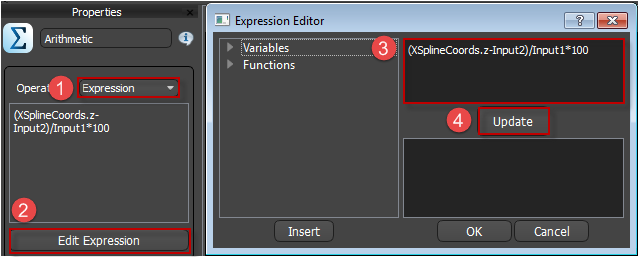
- Now create the equation. Connect Existing Height to Input 1 and Top+Bottom Height to Input 2 of the Arithmetic operator. Set the Operation type to Expression and open the Expression Editor. To translate our equation desired_height/geometry_height*100 to RailClone, enter (XSplineCoords.z-Input2)/Input1*100 in the expression editor and hit Update.
![Building Bridges-int5.png]()
- If you change the shape of the spline the height of the piers will now update automatically. If you change the Z position of the RailClone object you'll notice it doesn't update, this is because RailClone is not being prompted to re-evaluate its rules by this action. To update simply reselect the spline in the viewport.
Conclusion
Having completed this tutorial you will have a a spline with an adjustable height that uses a single spline to define the deck path and the RailClone pivot for the ground level. The same principles can easily be applied to other beam and truss bridge styles and may be adapted to create more complex bridges like suspension,arch, and cantilever. Stay tuned for future training, or for more information about many aspects of RailClone's features please see our reference section or visit the tutorials page for more Tips&Tricks videos and in-depth tutorials.